 Kymco XCITING 500 - Service Manual > Battery/Charging System
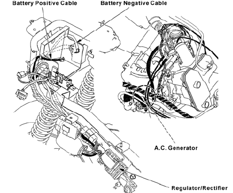
CHARGING SYSTEM LAYOUT
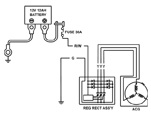
CHARGING CIRCUIT
SERVICE INFORMATION
GENERAL
CAUTION
- The battery gives off explosive gases; keep sparks, flames. Provide adequate ventilation when charging.
- The battery contains sulfuric acid (electrolyte). Contact with skin
or eyes may cause severe burns. Wear protective clothing and a face shield.
- If electrolyte gets on your skin, flush with water.
- If electrolyte gets in your eyes, flush with water for at least 15 minutes and call a physician immediately.
- Electrolyte is poisonous.
- If swallowed, drink large quantities of water or milk and call your local Poison Control Center or physician immediately, KEEP OUT OF REACH OF CHILDREN.
- Always turn off the ignition switch before disconnecting any electrical component.
- Some electrical components may be damaged if terminals or connectors are connected or disconnected while the ignition switch is turned to "ON" and current is present.
- For extended storage, remove the battery, give it a full charge, and store it in a cool, dry place.
- For a battery remaining in a shorted vehicle, disconnect the negative battery cable from the battery.
- The battery caps should not be removed. Attempting to remove the sealing caps from the cells may damage the battery.
- The maintenance free battery must be replaced when it reaches the end of its service life.
- The battery can be damaged if overcharged or undercharged, or if left to discharge for long period. These same conditions contribute to shortening the "life span" of the battery. Even under normal use, the performance of the battery deteriorates after 2-3 years.
- Battery voltage may recover after battery charging, but under heavy load, the battery voltage will drop quickly and eventually die out. For this reason, the charging system is often suspected as the problem. Battery overcharge often results from problems in the battery itself, which may appear to be an overcharging symptom. If one of the battery cells is shorted and battery voltage does not increase, the regulator/rectifier supplies excess voltage to the battery. Under these conditions, the electrolyte level goes down quickly.
- Before troubleshooting the charging system, check for proper use and
maintenance of the battery.
Check if the battery is frequently under heavy load, such as having the headlight and taillight on for long periods of time without riding the vehicle.
- The battery self-discharge when the vehicle is not in use, for this reason, charge the battery every 2 weeks to prevent sulfate from occurring.
- Filling a new battery with electrolyte will produce some voltage, but in order to achieve its maximum performance, always charge the battery. Also, the battery life is lengthened when it is initially charged.
- When checking the charging system, always follow the steps in the troubleshooting flow chart.
- For alternator service, refer to section 12.
BATTERY CHARGING
- This model comes with a maintenance free (MF) battery. Remember the
following about MF batteries.
- Use only the electrolyte that comes with the battery.
- Use all of the electrolyte
- Seal the battery properly
- Never open the seals again
- For battery charging, do not exceed the charging current and time specified on the battery. Using excessive current or extending the charging time may damage the battery.
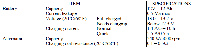
SPECIFICATIONS
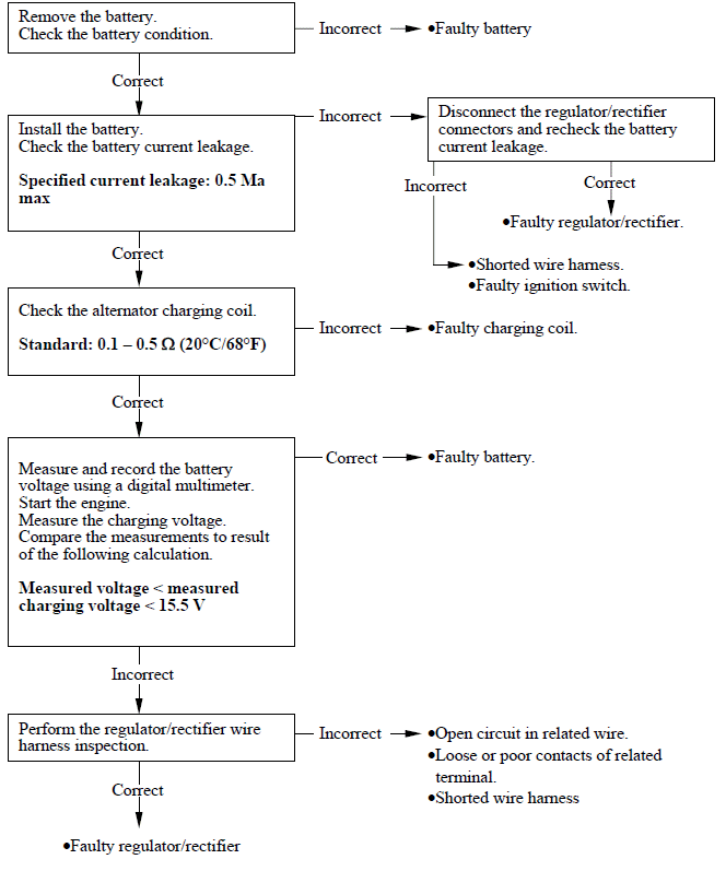
TROUBLESHOOTING
Battery is damaged or weak
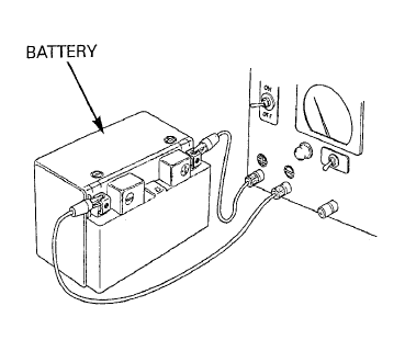
BATTERY
REMOVAL/INSTALLATION
Unlock and open the seat.
Turn ignition switch OFF.
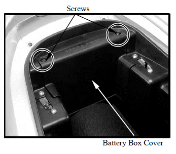
Remove the screws and battery box cover.
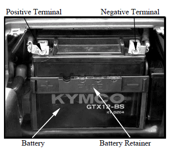
Remove the battery retainer.
With the ignition switch to "OFF" disconnect the negative (-) terminal lead from the battery first, then disconnect the positive (+) terminal lead.
Pull out the battery from the battery box.
Installation is in the reverse order of removal.
After connecting the battery cables, coat the terminals with grease.
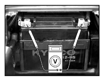
VOLTAGE INSPECTION
Remove the battery cover (see above).
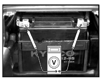
Measure the battery voltage using a commercially available digital multimeter.
Voltage (20ÂşC/68ÂşC):
Fully charged: 13.0-13.2 V
Under charged: below 12.3 V
BATTERY CHARGING
Remove the battery.
Connect the charger positive (+) cable to the battery positive (+) terminal.
Connect the charger negative (-) cable to the battery negative (-) terminal.
Turn the power ON/OFF at the charger, not at the battery terminals.
Charging current time:
Standard: 1.4 A/5-10 hours
Quick: 5.5 A/0.5 hours
Quick charging should only be done in an emergency; slow charging is preferred.
For battery charging, do not exceed the charging current and time specified on the battery. Using excessive current or extending the charging time may damage the battery.
CHARGING SYSTEM INSPECTION
Remove the battery cover.
CURRENT LEAKAGE TEST
Turn the ignition switch OFF, disconnect the negative (-) cable from the battery.
Connect the ammeter (+) probe to the negative (-) cable and the ammeter (-) probe to the battery (-) terminal.
With the ignition switch OFF, check for current leakage.
When measuring current using a tester, set it to a high range, and then bring the range down to an appropriate level. Current flow higher than the range selected may blow out the fuse in the tester.
While measuring current, do not turn the ignition switch ON. A sudden surge of current may blow out the fuse in the tester.
Specified current leakage: 0.5 Ma max.
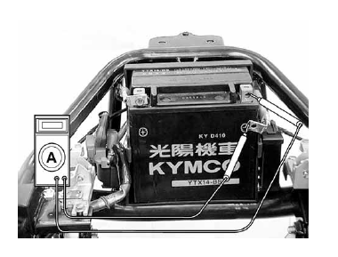
If current leakage exceeds the specified value, a shorted circuit is likely.
Locate the short by disconnecting connections one by one and measuring the current.
CHARGING VOLTAGE INSPECTION
Be sure that the battery is in good condition before performing this test.
Do not disconnect the battery or any cable in the charging system without first switching off the ignition switch. Failure to follow this precaution can damage the tester or electrical components.
Start the engine and warm it up to the operating temperature; stop the engine.
Connect the multimeter between the positive and negative terminals of the battery.
To prevent short, make absolutely certain which are the positive and negative terminals or cable.
With the headlight on and turned to the high beam position, restart the engine.
Measure the voltage on the multimeter when the engine runs at 5000 min-1 (rpm).
Standard:
Measured battery voltage <
Measure charging voltage (see above) <15.5 V
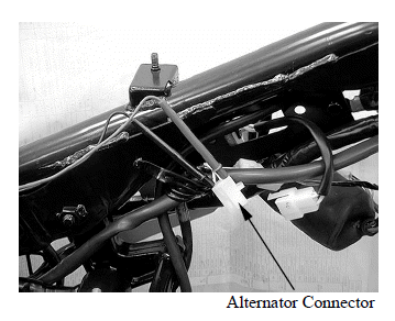
ALTERNATOR CHARGING COIL
INSPECTION
Remove the luggage box.
Disconnect the alternator connector.
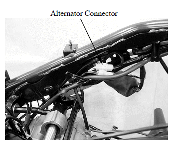
Measure the resistance between each Yellow wire terminals.
Standard: 0.1-0.5 Ω (20ºC/68ºF)
Check for continuity between each Yellow wire terminal of the alternator side connector and ground.
There should be continuity.
Replace the alternator stator if resistance is out of specification, or if any wire has continuity to ground.
Refer to section 12 for alternator stator replacement.
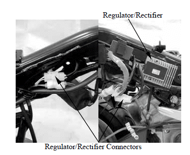
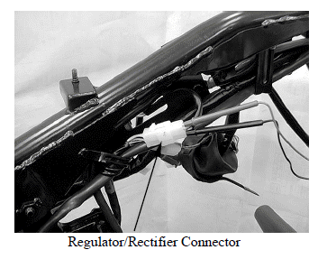
REGULATOR/RECTIFIER
WIRE HARNESS INSPECTION
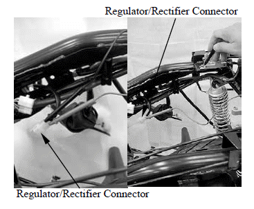
Remove the luggage box.
Disconnect the regulator/rectifier connectors.
Check the connectors for loose contacts of corroded terminals.
Battery line
Measure the voltage between the Red/White wire terminal and ground.
There should be battery voltage at all times.
Ground line
Check the continuity between the Green wire terminal and ground.
There should be continuity at all times.
Charging coil line
Measure the resistance between each Yellow wire terminals.
Standard: 0.1-0.5 Ω (20ºC/68ºF)
Check for continuity between each Yellow wire terminal and ground.
There should be no continuity.
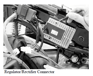
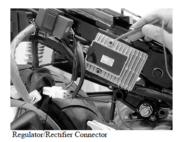
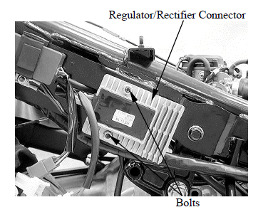
REMOVAL/INSTALLATION
Remove the side body cover.
Disconnect the regulator/rectifier connectors.
Remove the two bolts, regulator/rectifier and stay.
Installation is in the reverse order of removal.
See also:
 Kymco XCITING 500 - Service Manual > Rear/parking brake caliper
REMOVAL Remove the muffler. Drain the rear brake hydraulic system. Disconnect the parking brake cable from the brake arm. Remove the pad pin plug and loosen the pad pin.
Kymco XCITING 500 - Service Manual > Ignition System
IGNITION SYSTEM LAYOUT IGNITION CIRCUIT