 Kawasaki J300 - Service manual > Cable, Wire, and Hose Routing
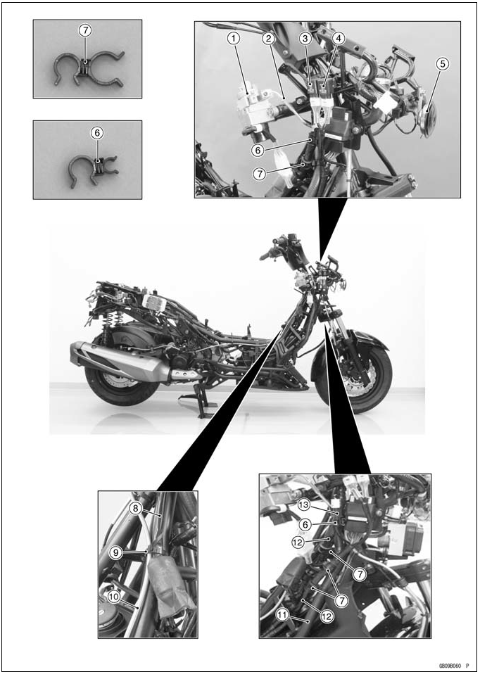
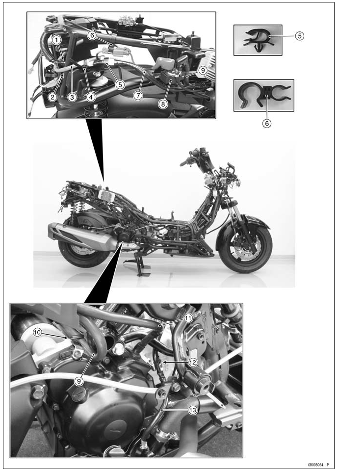
Appendix / Cable, Wire, and Hose Routing
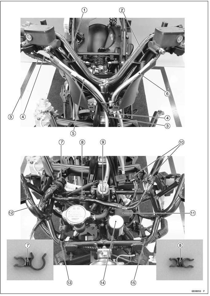
- Right Switch Housing Lead
- Left Switch Housing Lead
- Throttle Cable (Accelerator)
- Throttle Cable (Decelerator)
- Front Brake Hose
- Rear Brake Hose
- Clamp (Hold the main harness and fairing bracket.)
- Clamp (Hold the meter lead and fairing bracket.)
- Vehicle-down Sensor
- Meter Lead Connectors
- Red Oil Pressure Warning Indicator Light Controller
- Main Harness
- Band (Hold the main harness.)
- Turn Signal Relay
- Band (Hold the main harness.)
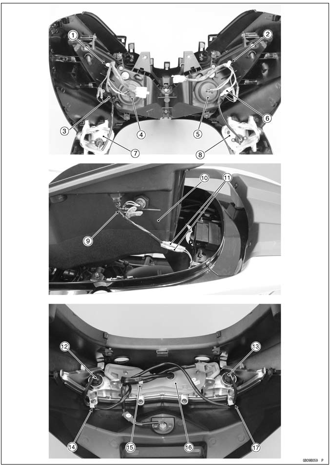
- Clamp (Hold the left headlight leads and left city light leads.)
- Clamp (Hold the right headlight leads and right city light leads.)
- Front Left Turn Signal Light Lead Connector
- Left Headlight
- Right Headlight
- Front Right Turn Signal Light Lead Connector
- Front Left Turn Signal Light
- Front Right Turn Signal Light
- Band (Hold the storage box light lead and storage box right switch lead.)
- Storage Box
- Storage Box Light Switch Lead Connectors
- Rear Right Turn Signal Light
- Rear Left Turn Signal Light
- Clamp (Hold the rear right turn signal light lead.)
- Clamp (Hold the tail/brake light lead.)
- Tail/Brake Light
- Clamp (Hold the rear left turn signal light lead.)
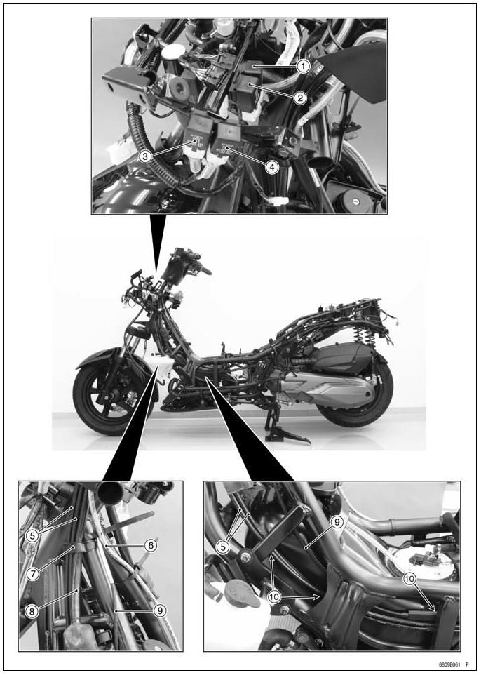
- Ignition Switch
- Seat Lock Cable
- Fuel Pump Relay
- ECU Relay
- Horn
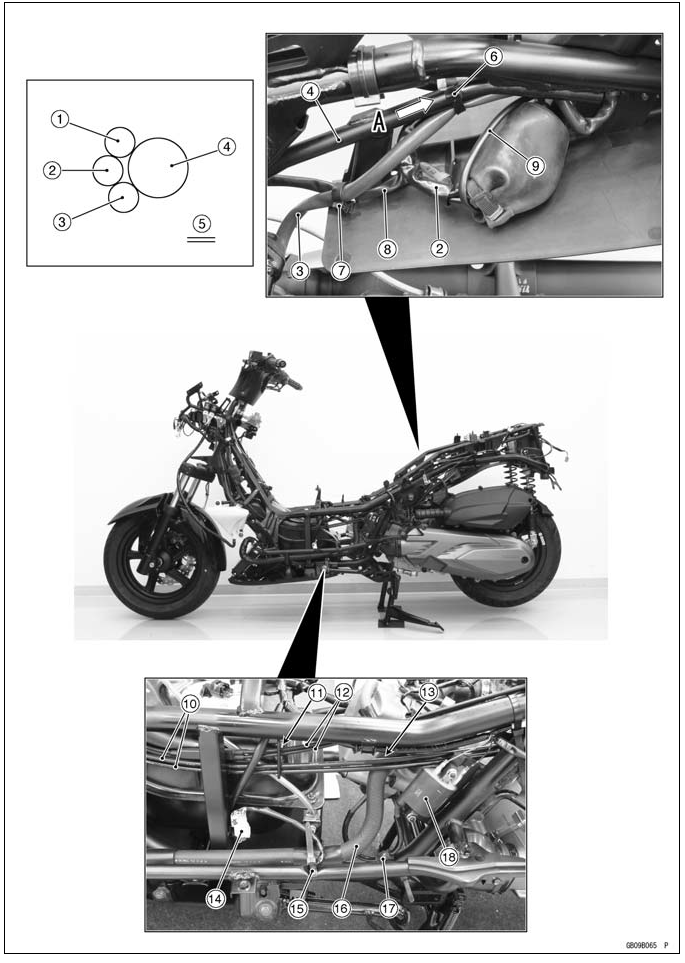
- Clamp (Hold the speed sensor (front wheel rotation sensor) lead connector and main harness.)
- Clamps (Hold the water hose and main harness.)
- Right Switch Housing Lead
- Band (Hold the right switch housing lead and rear brake hose.)
- Rear Brake Hose
- Water Hose
- Main Harnesses
- Speed Sensor (Front Wheel Rotation Sensor) Lead Connector
- Fan Relay
- Starter Relay 1
- High Beam Headlight Relay
- Low Beam Headlight Relay
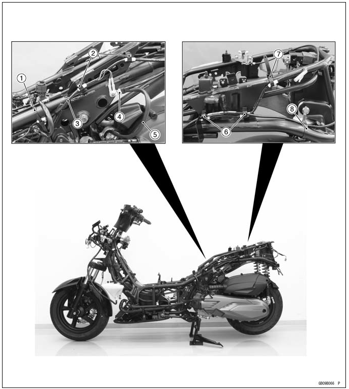
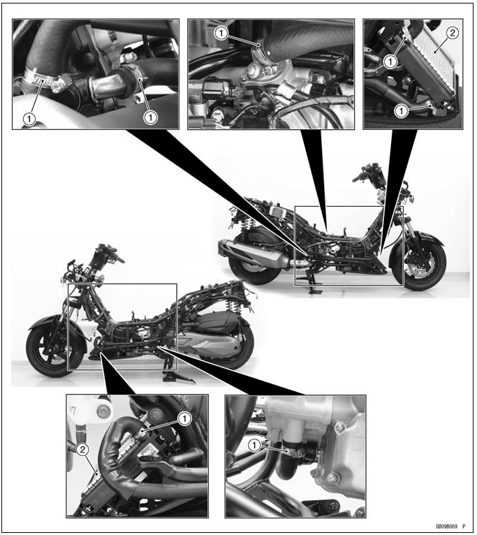
- Throttle Cables
- Rear Brake Hose
- Run the throttle cables and left switch housing lead to the inside of the guide.
- Left Switch Housing Lead
- Seat Lock Cable
- Run the throttle cables and seat lock cable to the inside of the frame.
- Run the fuel overflow hose into the hole of bracket.
- Fuel Overflow Hose
- Hold the main harness with the hook of the frame.
- Main Harness
- Rear Brake Hose
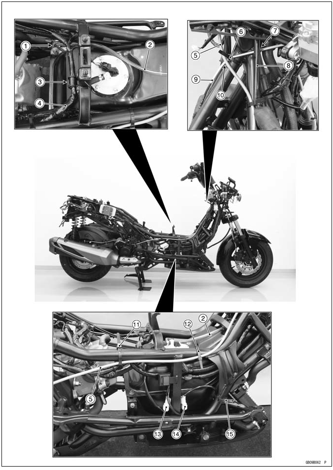
- Band (Hold the seat lock cable.)
- Run the seat lock cable under the right switch housing lead.
- Right Switch Housing Lead
- Seat Lock Cable
- Run the seat lock cable under the rear brake hose.
- Band (Hold the rear brake hose and main harness.)
- Band (Hold the rear brake hose.)
- EMI Filter Lead Connector (fixed on the stay)
- Radiator Fan Lead Connector (fixed on the stay)
- Band (Hold the radiator fan lead.)
- Regulator/Rectifier
- Aluminum Plate
- Clamps (Hold the main harness and frame.)
- Main Harness
- Alternator Lead
- Starter Motor Cable
- Frame Ground Terminal (on the upper)
- Frame Ground Terminal (on the lower)
- Oxygen Sensor Lead Connector
- Rear Brake Hose
- Band (Hold the rear brake hose.)
- Oxygen Sensor
- Run the main harness to the inside of the frame.
- Run the battery (+) cable to the outside of the frame.
- Battery (+) Cable
- Band (Hold the battery (+) cable and main harness.)
- Clamp (Hold the main harness.)
- Clamp (Hold the battery (+) cable connector.)
- Main Harness
- Starter Relay 2
- Starter Motor Cable
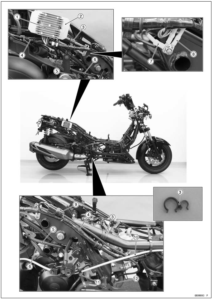
- Clamp (Hold the starter motor cable.)
- Alternator Lead
- Clamp (Hold the water bypass hose.)
- Water Bypass Hose
- Main Harness
- Regulator/Rectifier Lead
- Starter Motor Cable
- Frame
- View from A
- Band (Hold the main harness, regulator/rectifier lead and starter motor cable.)
- Clamp (Hold the alternator lead and starter motor cable.)
- Alternator Lead
- Starter Relay 2 Lead
- Throttle Cables
- Run the throttle cables and seat lock cables into the guide.
- Seat Lock Cables
- Run the throttle cables to the outside of the water hose.
- Side Stand Switch Lead Connector (fixed on the stay)
- Band (Hold the side stand switch lead.)
- Water Hose
- Clamp (Hold the spark plug cable.)
- Ignition Coil
- Band (Hold the main harness.)
- Clamps (Hold the main harness.)
- Main Harness
- Frame Ground Terminal (on the upper)
- Battery (-) Cable
- Clamps (Hold the main harness and battery (-) cable.)
- Band (Hold the main harness.)
- Band (Hold the battery (-) cable.)
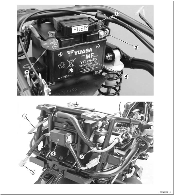
- Fuse Box
- Battery (+) Cable
- Battery (-) Cable
- Battery
- Tail/Brake Light Lead Connector
- Hazard Control Unit
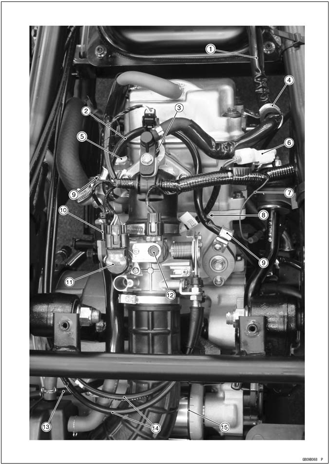
- Fuel Hose
- Water Bypass Hose
- Fuel Injector
- Clamp (Hold the fuel hose.)
- Water Temperature Sensor (ECU)
- Water Temperature Sensor (Meter) Lead
- Oil Pressure Switch Lead
- Run the water temperature sensor (meter) lead under the water bypass hose.
- Clamps (Hold the water bypass hose.)
- Throttle Sensor
- Idle Speed Control Valve Actuator
- Intake Air Pressure Sensor
- Battery (-) Cable
- Throttle Cables
- Starter Motor
- Water Hose Clamps
- Radiator
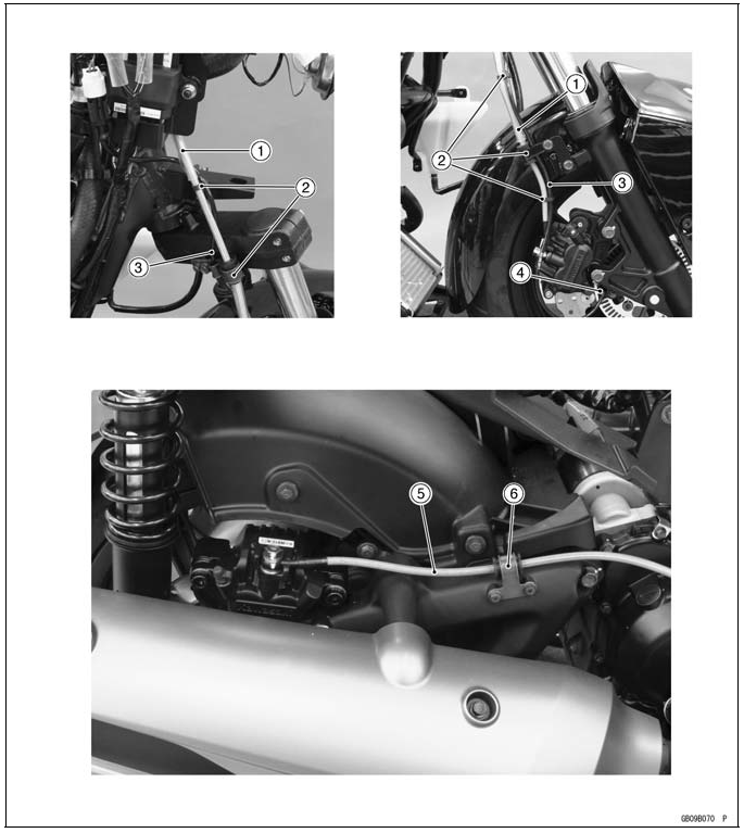
- Front Brake Hose
- Clamps (Hold the speed sensor (front wheel rotation sensor) lead and front brake hose.)
- Speed Sensor (Front Wheel Rotation Sensor) Lead
- Speed Sensor (Front Wheel Rotation Sensor)
- Rear Brake Hose
- Clamp (Hold the rear brake hose.)
ABS Equipped Model
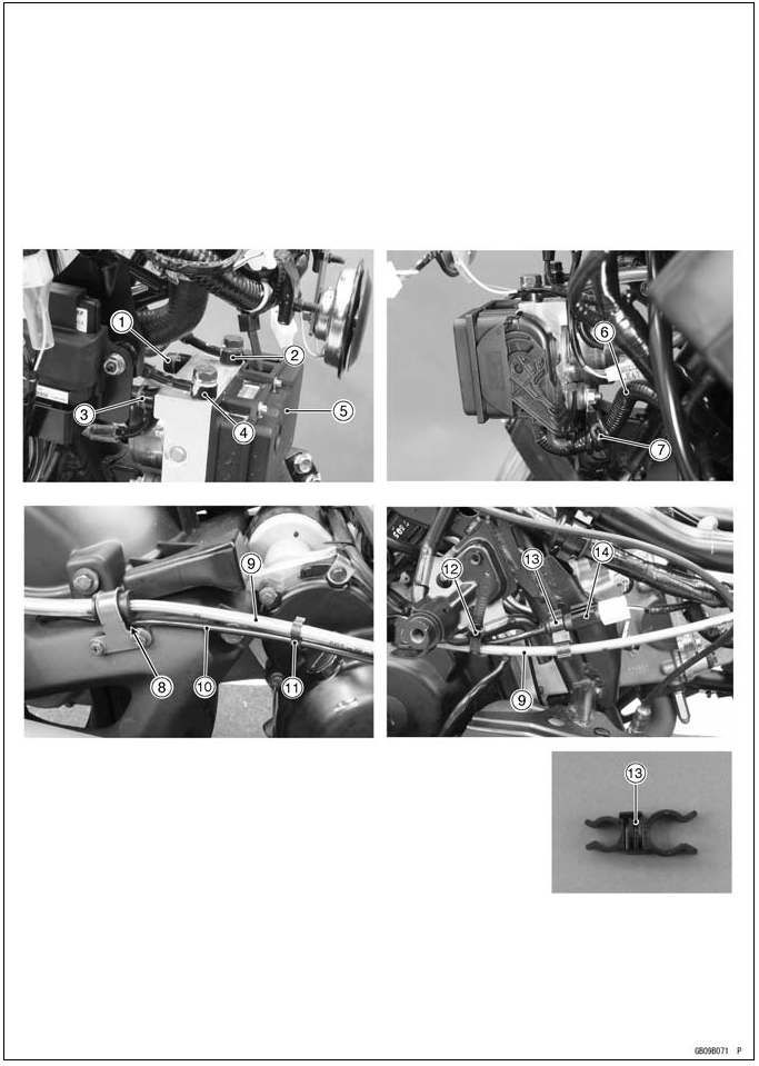
- To Rear Master Cylinder
- To Rear Caliper
- To Front Master Cylinder
- To Front Caliper
- ABS Hydraulic Unit
- ABS Hydraulic Unit Lead
- Clamp (Hold the ABS hydraulic unit lead.)
- Run the rear wheel rotation sensor lead under the brake hose held with the clamp.
- Rear Brake Hose
- Rear Wheel Rotation Sensor Lead
- Clamp (Hold the rear wheel rotation sensor lead and rear brake hose.)
- Band (Hold the rear wheel rotation sensor lead and rear brake hose.)
- Clamp (Hold the rear wheel rotation sensor lead connector and rear brake hose.)
- Rear Wheel Rotation Sensor Lead Connector
See also:
 Kawasaki J300 - Service manual > Troubleshooting Guide
NOTE Refer to the Fuel System chapter for most of DFI trouble shooting guide. This is not an exhaustive list, giving every possible cause for each problem listed. It is meant simply as a rough guide to assist the troubleshooting for some of the more common difficulties.