 Kawasaki J300 - Service manual > ECU
ECU Removal
NOTICE Never drop the ECU especially on a hard surface.
Such a shock to the ECU can damage it.
- Remove:
Front Fairing (see Front Fairing Removal in the Frame chapter)
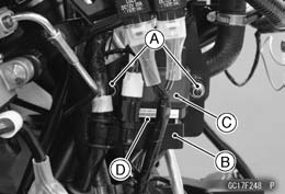
Nuts [A]
Bracket [B]
ECU [C] - Disconnect the ECU connector [D].
ECU Installation
- Installation is the reverse of removal.
- Reset the throttle sensor position and idle speed control valve actuator position (see How to Reset Throttle Sensor Position and Idle Speed Control Valve Actuator Position).
ECU Power Supply Inspection
- Remove the front fairing (see Front Fairing Removal in the Frame chapter).
- Visually inspect the ECU connectors.
If the connector is clogged with mud or dust, blow it off with compressed air.
- Remove the ECU (see ECU Removal).
- Visually inspect the terminals [A] of the ECU and main harness
connector.
If the terminals of the ECU connector are damaged, replace the ECU.
If the terminals of the main harness connectors are damaged, replace the main harness.
- Turn the ignition switch off.
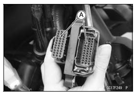
- Disconnect the ECU connector [A].
- Set a tester [B] and check the following wiring for continuity.
ECU Grounding Continuity Inspection
Connections:
(I) G/P leads (ECU terminal 9 [C] or 10 [D]) ‚Üê‚Üí Battery (-) Terminal
(II) Engine Ground ‚Üê‚Üí Battery (-) Terminal
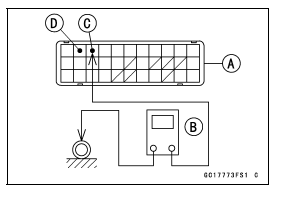
Criteria:
Both: about 0 Ω
If no continuity, check the connectors, the engine ground lead, or main harness, and repair or replace them if necessary.
If the wiring is good, check the power source voltage of the ECU.
NOTE
- Be sure the battery is fully charged.
- Connect the ECU connectors.
- Connect a digital meter [A] to the connector [B] with the needle adapter set.
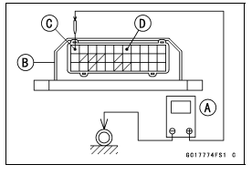
Special Tool - Needle Adapter Set: 57001-1457
ECU Power Supply Inspection
Connections:
(I)
Digital Meter (+) ‚Üí Terminal 1 (BK) [C]
Digital Meter (-) ‚Üí Battery (-) Terminal
(II)
Digital Meter (+) ‚Üí Terminal 7 (R/W) [D]
Digital Meter (-) ‚Üí Battery (-) Terminal
Ignition Switch OFF:
Terminal 1 (BK): 0 V
Terminal 7 (R/W): Battery Voltage
Ignition Switch ON:
All: Battery Voltage
If the reading is out of the specification, check the following.
Ignition Fuse 15 A (see Fuse Inspection in the Electrical System chapter)
Charging/ECU Fuse 30 A (see Fuse Inspection in the Electrical System chapter)
ECU Relay (see Relay Circuit Inspection in the Electrical System chapter)
Power Source Wiring (see wiring diagram in this section)
- Reset the throttle sensor position and idle speed control valve actuator position (see How to Reset Throttle Sensor Position and Idle Speed Control Valve Actuator Position).
ECU Power Source Circuit
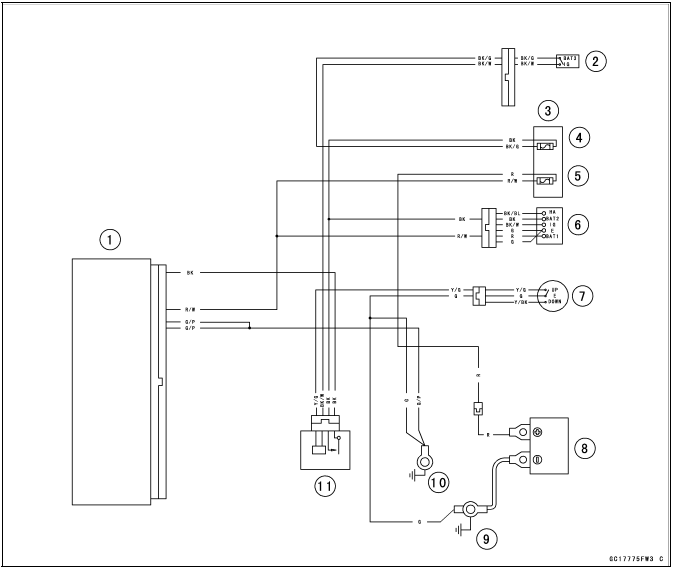
- ECU
- Engine Stop Switch
- Fuse Box
- Ignition Fuse 15 A
- Charging/ECU Fuse 30 A
- Ignition Switch
- Side Stand Switch
- Battery
- Engine Ground
- Frame Ground 1
- ECU Relay
DFI Power Source
ECU Fuse Removal
- Refer to the Fuse Box Fuse Removal in the Electrical System chapter.
ECU Fuse Installation
If a fuse fails during operation, inspect the DFI system to determine the cause, and then replace it with a new fuse of proper amperage.
- Refer to the Fuse Installation in the Electrical System chapter.
ECU Fuse Inspection
- Refer to the Fuse Inspection in the Electrical System chapter.
ECU Relay Removal/Installation
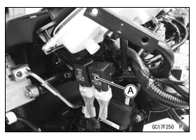
- Remove the front fairing (see Front Fairing Removal in the Frame chapter).
- Remove the ECU relay [A] and disconnect the connector.
ECU Relay Inspection
- Refer to the Relay Inspection in the Electrical System chapter.
See also:
 Kawasaki J300 - Service manual > Crankshaft Sensor (Service Code 66)
The crankshaft sensor has no power source, and when the engine stops, the crankshaft sensor generates no signals. Crankshaft Sensor Removal/Installation Refer to the Crankshaft Sensor Removal/Installation in the Electrical System chapter.
 Kawasaki J300 - Service manual > Fuel Line
Fuel Pressure Inspection NOTE Be sure the battery is fully charged. Remove the fuel hose (see Fuel Hose Replacement in the Periodic Maintenance chapter). Be sure to place a piece of cloth around the fuel outlet pipe of the fuel pump and the fuel pipe of the intake manifold.


