 Kawasaki J300 - Service manual > Exploded View, DFI System/Parts Location, Specifications, Special Tools
Exploded View
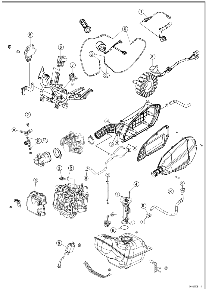
5. ECU
6. ECU Relay
7. Vehicle-down Sensor
8. Crankshaft Sensor
9. Ignition Coil
CL: Apply cable lubricant.
EO: Apply engine oil.
G: Apply grease.
R: Replacement Parts
DFI System
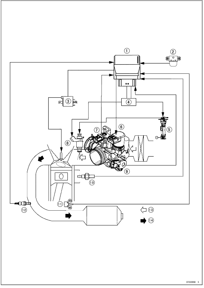
- ECU
- Vehicle-down Sensor
- Ignition Coil
- Fuel Pump Relay
- Fuel Pump
- Idle Speed Control Valve Actuator
- Intake Air Pressure Sensor
- Fuel Injector
- Throttle Senor
- Water Temperature Sensor (ECU)
- Crankshaft Sensor
- Oxygen Sensor
- Fresh Air
- Exhaust Gas
DFI System Wiring Diagram
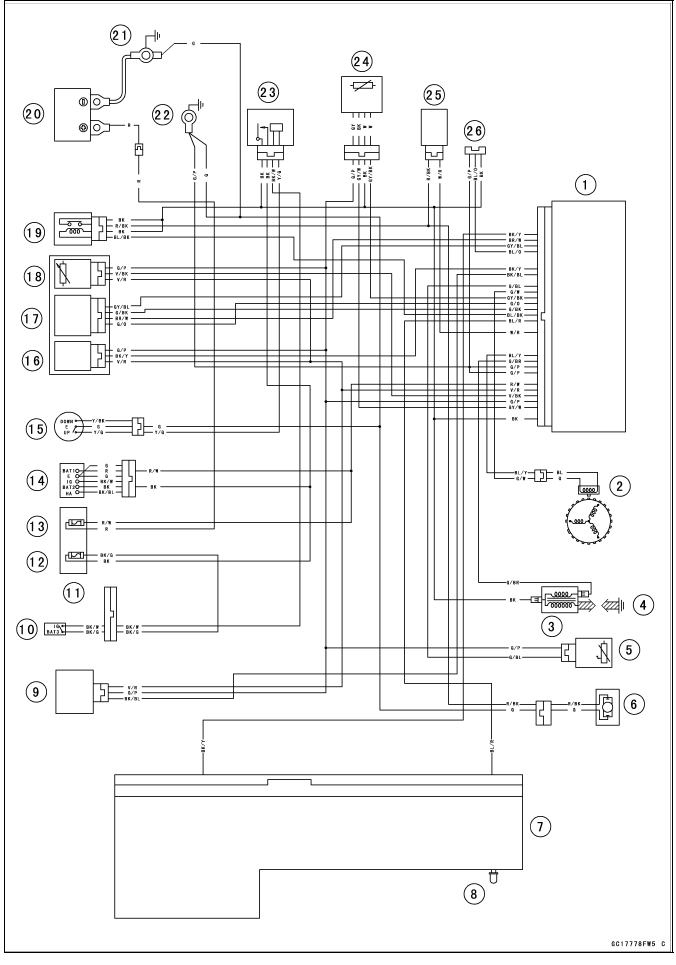
Part Names
- ECU
- Crankshaft Sensor
- Ignition Coil
- Spark Plug
- Water Temperature Sensor (ECU)
- Fuel Pump
- Meter Unit
- Yellow Engine Warning Indicator Light (LED)
- Vehicle-down Sensor
- Engine Stop Switch
- Fuse Box
- Ignition Fuse 10 A
- Charging/ECU Fuse 30 A
- Ignition Switch
- Side Stand Switch
- Intake Air Pressure Sensor
- Idle Speed Control Valve Actuator
- Throttle Sensor
- Fuel Pump Relay
- Battery
- Engine Ground
- Frame Ground 1
- ECU Relay
- Oxygen Sensor
- Fuel Injector
- Self-Diagnostic System Connector
Color Codes:
BK: Black
BL: Blue
BR: Brown
CH: Chocolate
DG: Dark Green
G: Green
GY: Gray
LB: Light Blue
LG: Light Green
O: Orange
P: Pink
PU: Purple
R: Red
V: Violet
W: White
Y: Yellow
Terminal Numbers of ECU Connectors
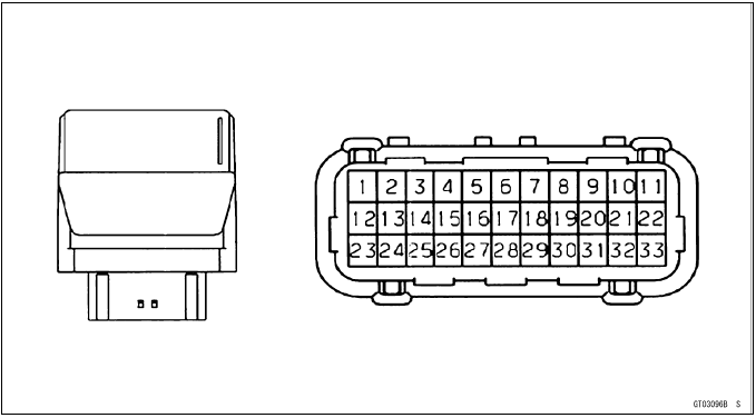
Terminal Names
- Ignition Power: BK
- Ground: G/P
- Oxygen Sensor: GY/W
- Ground for Sensors: G/P
- Throttle Sensor: V/BK
- Power Supply to Sensors: V/R
- Battery: R/W
- Radiator Fan Relay: G/BK
- Ground: G/P
- Ground: G/P
- Ignition Coil: G/BR
- Crankshaft Sensor (+): BL/Y
- Unused
- Unused
- Unused
- Fuel Injector: W/R
- Unused
- Yellow Engine Warning Indicator Light (LED): BL/R
- Fuel Pump Relay: BL/BK
- Idle Speed Control Valve B (-): G/BK
- Idle Speed Control Valve A (-): G/O
- Oxygen Sensor Heater: GY/BK
- Crankshaft Sensor (-): G/W
- Water Temperature Sensor: G/BL
- Unused
- Vehicle-down Sensor: BK/BL
- Intake Air Pressure Sensor: BK/Y
- Unused
- Unused
- Self-Diagnostic System: BL/O
- Idle Speed Control Valve B (+): GY/BL
- Idle Speed Control Valve A (+): BR/W
- Meter: BK/Y
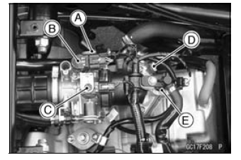
DFI Parts Location
Throttle Sensor [A]
Idle Speed Control Valve Actuator [B]
Intake Air Pressure Sensor [C]
Water Temperature Sensor (ECU) [D]
Fuel Injector [E]
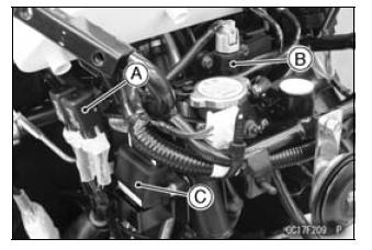
ECU Relay [A]
Vehicle-down Sensor [B]
ECU [C]
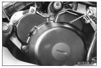
Crankshaft Sensor [A]
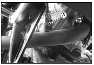
Oxygen Sensor [A]
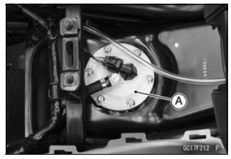
Fuel Pump [A]
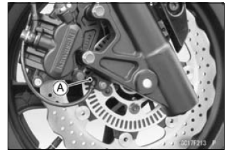
Speed Sensor (Front Wheel Rotation Sensor) [A]
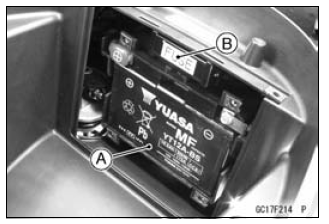
Battery [A]
Fuse Box (Charging/ECU Fuse 30 A) [B]
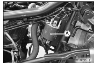
Ignition Coil [A]
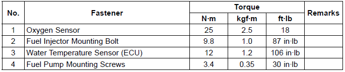
Specifications
Special Tools and Sealant
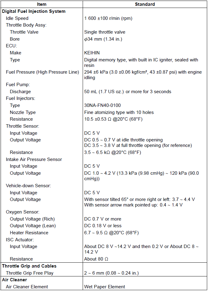
Oil Pressure Gauge, 5 kgf/cm²: 57001-125
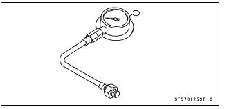
Fuel Pressure Gauge Adapter: 57001-1593
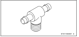
Peak Voltage Adapter: 57001-1415
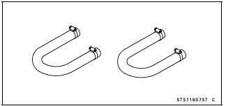
Fuel Hose: 57001-1607
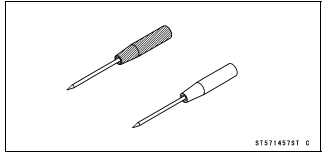
Needle Adapter Set: 57001-1457
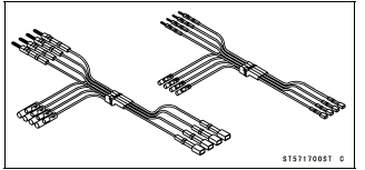
Measuring Adapter: 57001-1700
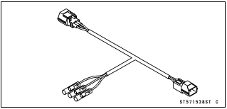
Throttle Sensor Setting Adapter: 57001-1538
Liquid Gasket, TB1211: 56019-120
See also:
 Kawasaki J300 - Service manual > DFI Servicing Precautions
DFI Servicing Precautions There are a number of important precautions that should be followed servicing the DFI system. This DFI system is designed to be used with a 12 V sealed battery as its power source. Do not use any other battery except for a 12 V sealed battery as a power source. Do not reverse the battery cable connections. This will damage the ECU. To prevent damage to the DFI parts, do not disconnect the battery cables or any other electrical connections when the ignition switch is on, or while the engine is running. Take care not to short the leads that are directly connected to the battery positive (+) terminal to the chassis ground. When charging, remove the battery from the motorcycle.