 Kymco XCITING 500 - Service Manual > Front Master Cylinder
REMOVAL
When removing the brake hose bolt, cover the end of the hose to prevent contamination.
Secure the hose to prevent fluid from leaking out.
Remove the upper handlebar cover.
Drain the front brake hydraulic system.
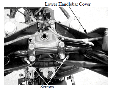
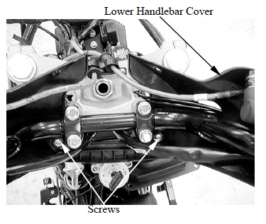
Remove the two screws and lower handlebar cover.
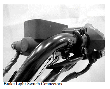
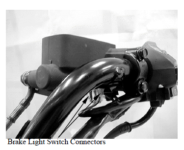
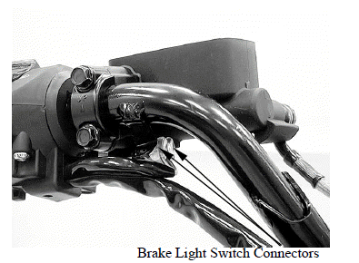
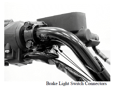
Disconnect the brake light connectors from front master cylinder.
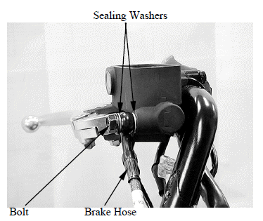
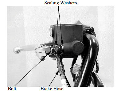
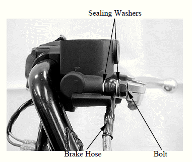
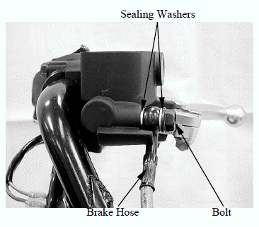
Remove the brake hose oil bolt, sealing washers and brake hose eyelet.
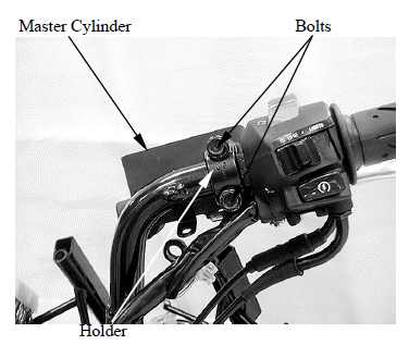
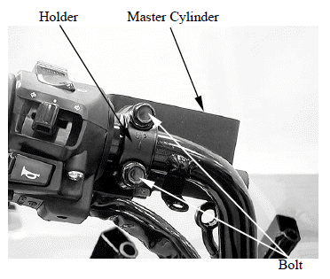
Remove the bolts from the master cylinder holder and remove the master cylinder assembly.
DISASSEMBLY
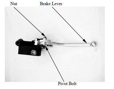
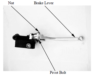
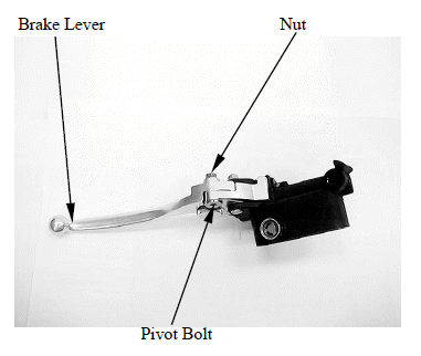
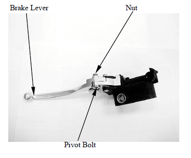
Remove the brake lever pivot bolt and nut.
Remove the brake lever.
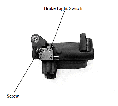
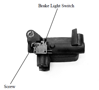
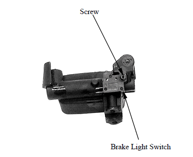
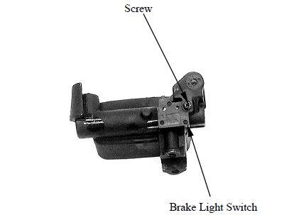
Remove the screw and brake light switch.
ASSEMBLY
Install the brake light switch and tighten the screw to the specified torque.
Torque: 1 N*m (0.1 kgf*m, 0.7 lbf*ft)
Apply silicone grease to the master piston tip.
Install the brake lever.
Apply silicone grease to the brake lever pivot bolt sliding surface.
Install and tighten the pivot bolt to the specified torque.
Torque: 6 N*m (0.6 kgf*m, 4.3 lbf*ft)
Install and tighten the pivot nut to the specified torque.
Torque: 6 N*m (0.6 kgf*m, 4.3 lbf*ft)
INSTALLATION
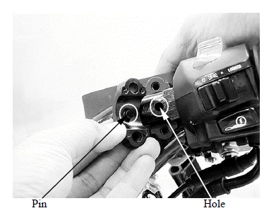
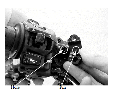
Align the pin on the master cylinder holder with the hole on the handlebar.
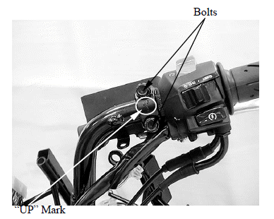
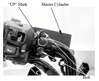
Install the front master cylinders and holders with the "UP" mark facing up.
Install the bolts and tighten the upper bolt first then tighten the lower bolt to the specified torque.
Torque: 12 N*m (1.2 kgf*m, 9 lbf*ft)
Rest the brake hose eyelet against the stopper.
Install the brake hose eyelet with the oil bolt and new sealing washers.
Tighten the oil bolt to the specified torque.
Torque: 35 N*m (3.5 kgf*m, 25 lbf*ft)
Connect the brake light switch connectors.
Fill the reservoir to the upper level and bleed the brake system.
REAR MASTER CYLINDER
REMOVAL
When removing the brake hose bolt, cover the end of the hose to prevent contamination.
Secure the hose to prevent fluid from leaking out.
Remove the upper handlebar cover.
Drain the combination brake hydraulic system.
Remove the two screws and lower handlebar cover.
Disconnect the brake light switch connectors from master cylinder.
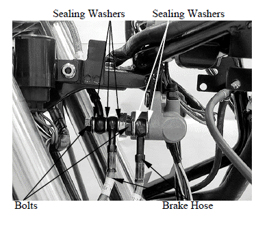
Remove the brake hose oil bolt, sealing washers and brake hose eyelet.
Remove the bolts from the master cylinder holder and remove the master cylinder assembly.
DISASSEMBLY
Remove the brake lever pivot bolt and nut.
Remove the brake lever.
Remove the screw and brake light switch.
ASSEMBLY
Install the brake light switch and tighten the screw to the specified torque.
Torque: 1 N*m (0.1 kgf*m, 0.7 lbf*ft)
Apply silicone grease to the master piston tip.
Install the brake lever.
Apply silicone grease to the brake lever pivot bolt sliding surface.
Install and tighten the pivot bolt to the specified torque.
Torque: 6 N*m (0.6 kgf*m, 4.3 lbf*ft)
Install and tighten the pivot nut to the specified torque.
Torque: 6 N*m (0.6 kgf*m, 4.3 lbf*ft)
INSTALLATION
Align the pin on the master cylinder holder with the hole on the handlebar.
Install the rear master cylinders and holders with the "UP" mark facing up.
Install the bolts and tighten the upper bolt first then tighten the lower bolt to the specified torque.
Torque: 12 N*m (1.2 kgf*m, 9 lbf*ft)
Rest the brake hose eyelet against the stopper.
Install the brake hose eyelet with the oil bolt and new sealing washers.
Tighten the oil bolt to the specified torque.
Torque: 35 N*m (3.5 kgf*m, 25 lbf*ft)
Connect the brake light switch connectors.
Fill the reservoir to the upper level and bleed the brake system.
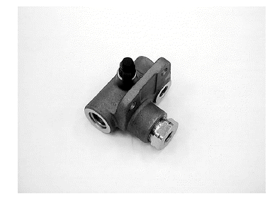
DELAY VALVE
REMOVAL
When removing the brake hose bolt, cover the end of the hose to prevent contamination.
Secure the hose to prevent fluid from leaking out.
Remove the front cover.
Drain the combination brake hydraulic system.
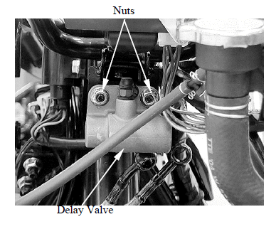
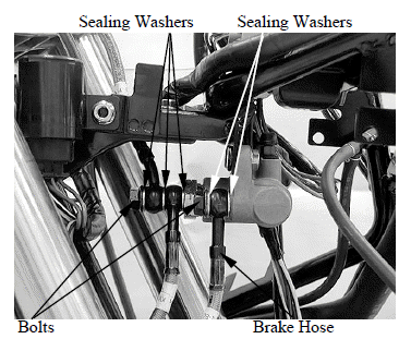
Remove the brake hose oil bolt, sealing washers and brake hose eyelets.
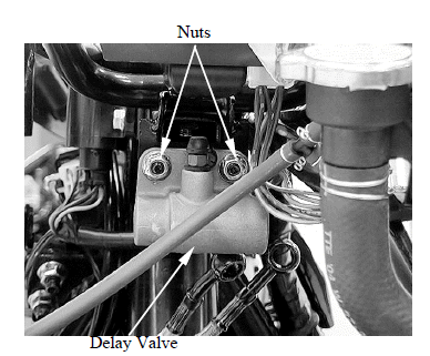
Remove the two nuts and delay valve.
INSTALLATION
Install the delay valve and tighten the nuts securely.
Install the brake hose eyelets and new sealing washers.
Tighten the brake hose bolt to the specified torque while rest the brake hose eyelet against the stopper on the delay valve.
Torque: 35 N*m (3.5 kgf*m, 25 lbf*ft)
Fill the reservoir to the upper level and bleed the brake system.
See also:
 Kymco XCITING 500 - Service Manual > Brake Pad
BRAKE PAD REPLACEMENT Front brake: Push the caliper pistons all the way in by pushing the caliper body inward to provide clearance for new pads.
Kymco XCITING 500 - Service Manual > Front Brake Caliper
REMOVAL Drain the front brake hydraulic system (left front brake caliper) or combination brake hydraulic system (right front brake caliper). Remove the brake pads. Remove the oil bolts, sealing washers and brake hose from the brake caliper.