 Kawasaki J300 - Service manual > Idle Speed Control Valve Actuator (Service Code 49)
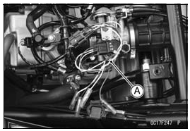
Idle Speed Control Valve Actuator Removal
NOTICE Never drop the idle speed control valve actuator especially on a hard surface. Such a shock to the actuator can damage it.
- Remove the storage box (see Storage Box Removal in the Frame chapter).
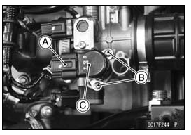
- Disconnect the idle speed control valve actuator connector [A].
- Remove:
Retainer Mounting Screws [B]
Idle Speed Control Valve Actuator [C] with Retainer
Idle Speed Control Valve Actuator Installation
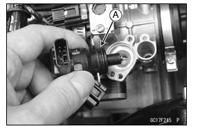
- Replace the O-ring [A] with a new one.
- Install the idle speed control valve actuator together with the
retainer, and tighten the retainer mounting screws.
If the idle speed control valve actuator is replaced, be sure to do the following procedures.
- Turn the ignition switch on.
- Turn the ignition switch off, and wait for 2 or 3 seconds.
- Inspect the idle speed (see Idle Speed Inspection in the Periodic Maintenance chapter).
- Reset the idle speed control valve actuator position (see How to Reset Throttle Sensor Position and Idle Speed Control Valve Actuator Position).
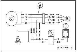
Idle Speed Control Valve Actuator Resistance Inspection
- Turn the ignition switch off.
- Remove the storage box (see Storage Box Removal in the Frame chapter).
- Disconnect the idle speed control valve actuator connector.
- Connect a digital meter to the idle speed control valve actuator.
- Measure the idle speed control valve actuator resistance.
Idle Speed Control Valve Actuator Resistance
Connections:
G/O lead [A] ŌåÉŌåÆ BR/W lead [B]
G/BK lead [C] ŌåÉŌåÆ GY/BL lead [D]
Standard: About 80 ╬®
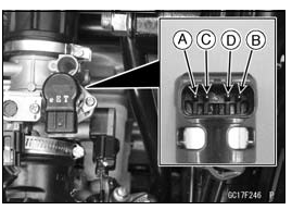
If the reading is out of the standard, replace the idle speed control valve actuator.
If the reading is within the standard, check the input voltage (see Idle Speed Control Valve Actuator Input Voltage Inspection).
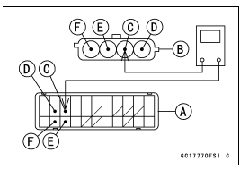
Idle Speed Control Valve Actuator Input Voltage Inspection
NOTE
- Be sure the battery is fully charged.
- Turn the ignition switch off.
- Disconnect the idle speed control valve actuator connector and connect the measuring adapter [A] between these connectors.
Main Harness [B]
Idle Speed Control Valve Actuator [C]
- Connect the peak voltage adapter [D] and a digital meter [E] to the measuring adapter leads.
Special Tools -
Peak Voltage Adapter: 57001-1415
Type: KEK-54-9-B
Measuring Adapter: 57001-1700
Idle Speed Control Valve Actuator Input Voltage
Connections to Adapter:
(I)
Digital Meter (+) ŌåÆ R (actuator G/O) lead
Digital Meter (-) ŌåÆ Frame Ground terminal
(II)
Digital Meter (+) ŌåÆ W (actuator G/BK) lead
Digital Meter (-) ŌåÆ Frame Ground terminal
(III)
Digital Meter (+) ŌåÆ Y (actuator GY/BL) lead
Digital Meter (-) ŌåÆ Frame Ground terminal
(IV)
Digital Meter (+) ŌåÆ BK (actuator BR/W) lead
Digital Meter (-) ŌåÆ Frame Ground terminal
- Measure the actuator input voltage with the engine stopped and with the connector joined.
- Turn the ignition switch on.
Input Voltage
Standard:
About DC 8 - 14.2 V and then 0.2 V or
About DC 8 - 14.2 V
- Turn the ignition switch off.
If the reading is out of the specification, remove the ECU and check the wiring for continuity between main harness connector.
- Disconnect the ECU and actuator connectors.
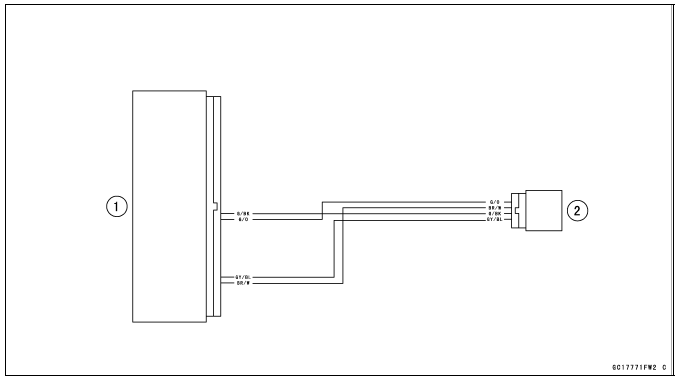
Wiring Continuity Inspection
ECU Connector [A] ŌåÉŌåÆ
Idle Speed Control Valve Actuator Connector [B]
G/BK lead (ECU terminal 20) [C]
G/O lead (ECU terminal 21) [D]
GY/BL lead (ECU terminal 31) [E]
BR/W lead (ECU terminal 32) [F]
If the wiring is good, check the ECU for its ground and power supply (see ECU Power Supply Inspection).
If the ground and power supply are good, replace the ECU (see ECU Removal/Installation).
- Reset the idle speed control valve actuator position (see How to Reset Throttle Sensor Position and Idle Speed Control Valve Actuator Position).
Idle Speed Control Valve Actuator Circuit
- ECU
- Idle Speed Control Valve Actuator
See also:
 Kawasaki J300 - Service manual > Oxygen Sensor Heater (Service Code 45)
Oxygen Sensor Heater Removal/Installation The oxygen sensor heater is built in the oxygen sensor. So, the heater itself can not be removed. Remove the oxygen sensor (see Oxygen Sensor Removal) in the Electrical System chapter).
Kawasaki J300 - Service manual > Crankshaft Sensor (Service Code 66)
The crankshaft sensor has no power source, and when the engine stops, the crankshaft sensor generates no signals. Crankshaft Sensor Removal/Installation Refer to the Crankshaft Sensor Removal/Installation in the Electrical System chapter.