 Kawasaki J300 - Service manual > Vehicle-down Sensor (Service Code 15)
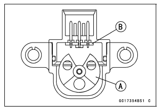
This sensor has a weight [A] with two magnets inside, and sends a signal to the ECU. But when the motorcycle banks 65┬║ or more to either side (in fact falls down), the weight turns and the signal changes. The ECU senses this change, and stops the fuel pump relay, the fuel injector and the ignition system.
Hall IC [B]
When the motorcycle is down, the ignition switch is left ON. If the starter button is pushed, the electric starter turns but the engine does not start. To start the engine again, raise the motorcycle, turn the ignition switch to OFF, and then turn it to ON.
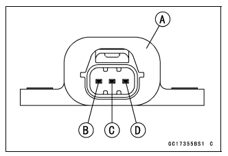
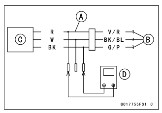
Vehicle-down Sensor [A]
Ground Terminal [B]: G/P
Output Terminal [C]: BK/BL
Input Terminal [D]: V/R
Vehicle-down Sensor Removal
NOTICE Never drop the vehicle-down sensor especially on a hard surface. Such a shock to the sensor can damage it.
- Remove the front center cover (see Front Center Cover Removal in the Frame chapter).
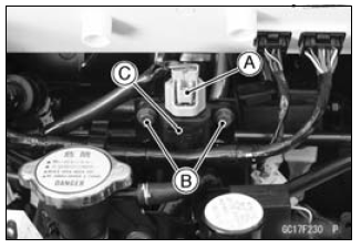
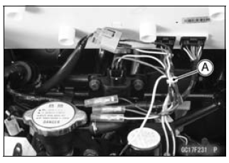
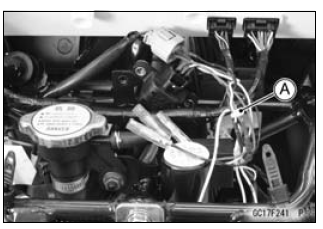
- Disconnect the vehicle-down sensor connector [A].
- Remove:
Bolts [B]
Vehicle-down Sensor [C]
Vehicle-down Sensor Installation
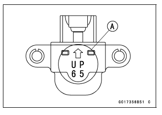
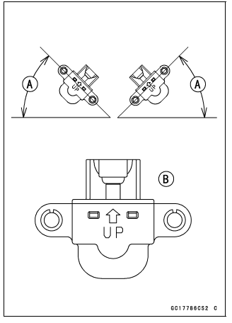
- The UP mark [A] of the sensor should face upward.
WARNING Incorrect installation of the vehicle-down sensor could cause sudden loss of engine power. The rider could lose balance during certain riding situations for an accident resulting in injury or death.
Ensure that the vehicle-down sensor is held in place by the sensor bracket.
- Tighten the vehicle-down sensor bolts.
Vehicle-down Sensor Input Voltage Inspection
NOTE
- Be sure the battery is fully charged.
- Turn the ignition switch off.
- Remove the front center cover (see Front Center Cover Removal in the Frame chapter).
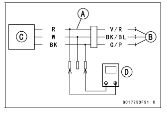
- Disconnect the vehicle-down sensor connector and connect the measuring
adapter [A] between these connectors.
Main Harness [B]
Vehicle-down Sensor [C]
Special Tool - Measuring Adapter: 57001-1700
- Connect a digital meter [D] to the measuring adapter leads.
Vehicle-down Sensor Input Voltage
Connections to Adapter:
Digital Meter (+) ŌåÆ R (sensor V/R) lead
Digital Meter (-) ŌåÆ BK (sensor G/P) lead
- Measure the input voltage with the engine stopped and with the connector joined.
- Turn the ignition switch on.
Input Voltage
Standard: DC 5 V
- Turn the ignition switch off.
If the reading is within the standard, check the output voltage (see Vehicle-down Sensor Output Voltage Inspection).
If the reading is out of the standard, remove the ECU and check the wiring for continuity between main harness connectors.
- Disconnect the ECU and sensor connectors.
Wiring Continuity Inspection
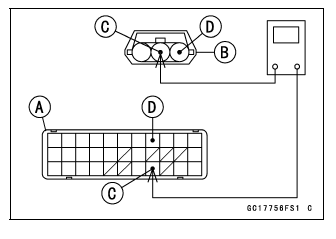
ECU Connector [A] ŌåÉŌåÆ
Vehicle-down Sensor Connector [B]
V/R lead (ECU terminal 6) [C]
G/P lead (ECU terminal 4) [D]
If the wiring is good, check the ECU for its ground and power supply (see ECU Power Supply Inspection).
If the ground and power supply are good, replace the ECU (see ECU Removal/Installation).
Vehicle-down Sensor Output Voltage Inspection
- Remove the vehicle-down sensor.
- Connect the measuring adapter [A] to the vehicle-down sensor connectors.
Special Tool - Measuring Adapter: 57001-1700
Main Harness [B]
Vehicle-down Sensor [C]
- Connect a digital meter [D] to the measuring adapter leads.
Vehicle-down Sensor Output Voltage
Connections to Adapter:
Digital Meter (+) ŌåÆ W (sensor BK/BL) lead
Digital Meter (-) ŌåÆ BK (sensor G/P) lead
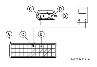
- Hold the sensor vertically.
- Measure the output voltage with the engine stopped, and with the connector joined.
- Turn the ignition switch on.
- Tilt the sensor 65┬║ or more [A] right or left, then hold the sensor almost vertical with the arrow mark pointed up [B], and measure the output voltage.
Output Voltage
Standard:
With sensor tilted 65┬║ or more right or left: DC 3.7 - 4.4 V
With sensor arrow mark pointed up: DC 0.4 - 1.4 V
- Turn the ignition switch off.
If the reading is out of the standard, replace the sensor.
If the reading is within the standard, remove the ECU and check the wiring for continuity between main harness connectors.
- Disconnect the ECU and sensor connectors.
Wiring Continuity Inspection
ECU Connector [A] ŌåÉŌåÆ
Vehicle-down Sensor Connector [B]
BK/BL lead (ECU terminal 26) [C]
G/P lead (ECU terminal 4) [D]
If the wiring is good, check the ECU for its ground and power supply (see ECU Power Supply Inspection).
If the ground and power supply are good, replace the ECU (see ECU Removal/Installation).
Vehicle-down Sensor Circuit
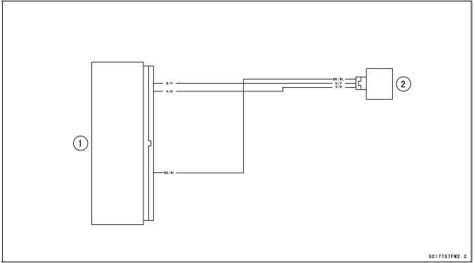
- ECU
- Vehicle-down Sensor
See also:
 Kawasaki J300 - Service manual > Intake Air Pressure Sensor (Service Code 09)
Intake Air Pressure Sensor Removal NOTICE Never drop the intake air pressure sensor especially on a hard surface. Such a shock to the sensor can damage it. Remove the storage box (see Storage Box Removal in the Frame chapter). Disconnect the intake air pressure sensor connector [A]. Remove: Screw [B] Plate [C] Intake Air Pressure Sensor [D]
Kawasaki J300 - Service manual > Oxygen Sensor - not activated (Service Code 17, Equipped Models)
Oxygen Sensor Removal/Installation Refer to the Oxygen Sensor Removal/Installation in the Electrical System chapter. Oxygen Sensor Inspection Remove: Storage Box (see Storage Box Removal in the Frame chapter) Oxygen Sensor Lead Connector [A] Connect the measuring adapter [A] between the harness connector and oxygen sensor lead connector.