 Kawasaki J300 - Service manual > ABS Hydraulic Unit Removal/Installation
ABS Hydraulic Unit Removal
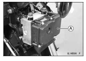
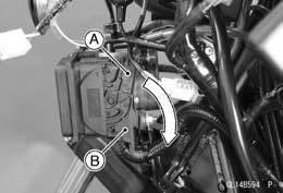
NOTICE The ABS hydraulic unit [A] has been adjusted and set with precision at the factory. Therefore, it should be handled carefully, never struck sharply, as with a hammer, or allowed to fall on a hard surface.
Be careful not to get water or mud on the ABS hydraulic unit.
- Drain the brake fluid from the front and rear brake lines.
- Drain the brake fluid through the bleed valve by pumping the brake lever and pedal.
- Clean the ABS hydraulic unit.
NOTICE Clean all fittings on the ABS hydraulic unit and the rear master cylinder because dirt around the banjo bolts could contaminate the brake fluid in the line during removal/installation.
Spread over a shop towel around the ABS hydraulic unit before removing the brake line so that brake fluid does not leak on the parts.
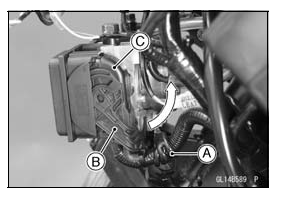
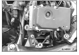
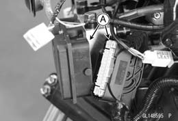
- Open the clamp [A].
- Pull the lever [B] upward to disconnect the ABS hydraulic unit connector [C].
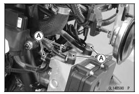
- Remove:
Brake Pipe Banjo Bolts [A]
NOTICE Brake fluid quickly ruins painted plastic surfaces; any spilled fluid should be completely washed away immediately.
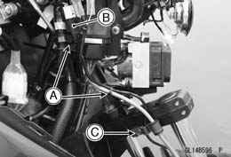
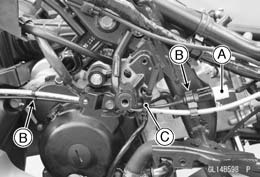
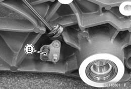
- Remove the bolts [A].
- Clear the projection [B], and remove the ABS hydraulic unit [C] together with the bracket.
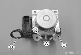
- Remove:
ABS Hydraulic Unit Mounting Nuts [A]
Clamp [B]
Bracket [C]
NOTICE The ABS hydraulic unit has been adjusted and set with precision at the factory. Do not try to disassemble and repair the ABS hydraulic unit.
ABS Hydraulic Unit Installation
NOTICE Brake fluid quickly ruins painted plastic surfaces; any spilled fluid should be completely washed away immediately.
- Install the bracket and clamp to the ABS hydraulic unit, and tighten the
ABS hydraulic unit mounting nuts.
Torque - ABS Hydraulic Unit Mounting Nuts: 7.8 N*m (0.80 kgf*m, 69 in*lb)
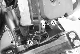
- Insert the projection [A] into the grommet [B], and tighten the bolts.
- Replace the washers that are on each side of hose fitting with new ones.
- Install the brake hoses (see Cable, Wire, and Hose Routing section in the Appendix chapter).
- Tighten:
Torque - Brake Hose Banjo Bolts: 34 N*m (3.5 kgf*m, 25 ft*lb)
- Pull the lever [A] downward to connect the ABS hydraulic unit connector [B].
- Hold the ABS hydraulic unit lead with the clamp.
- Bleed the brake line (see Brake Line Bleeding).
- Check the brake for good braking power, no brake drag, and no fluid leakage.
- Install the removed parts (see appropriate chapters).
ABS Hydraulic Unit Inspection
- Disconnect the ABS hydraulic unit connector (see ABS Hydraulic Unit Removal).
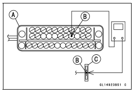
- Visually inspect the connector terminals [A].
Replace the ABS hydraulic unit or main harness if either of the terminals are cracked, bent, or otherwise damaged.
If the ABS hydraulic unit connector is clogged with mud or dust, blow it off with compressed air.
- Remove the ABS hydraulic unit (see ABS Hydraulic Unit Removal).
- Visually inspect the ABS hydraulic unit.
Replace the ABS hydraulic unit if any of them are cracked, or otherwise damaged.
Power Supply Inspection
- When the supply voltage is too low voltage or too high voltage, check
the ABS hydraulic unit connector (see ABS Hydraulic Unit Inspection).
If the connector is good, check the battery condition (see Charging Condition Inspection in the Electrical System chapter).
If the battery condition is good, check the charging voltage condition (see Charging Voltage Inspection in the Electrical System chapter).
ABS ECU Inspection
- Check the power supply voltage (see Power Supply Inspection).
If the power supply voltage is good, check the wiring continuity BL/O lead.
ABS Hydraulic Unit Lead Connector [A]
BL/O Lead Terminal [B]
Self-Diagnosis System Connector [C]
If the wiring is open, replace or repair the harness (see ABS System Wiring Diagram).
If the wiring is good, replace the ABS hydraulic unit.
ABS Motor Inspection
If the ABS motor has a problem, refer to the ABS Motor Relay Inspection.
Intake Valve and Outlet Valve Inspection
If the intake and outlet valves have a problem, refer to the ABS Solenoid Valve and Relay Inspection.
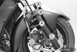
Front Wheel Rotation Sensor Removal
NOTICE The wheel rotation sensor should be handled carefully, never struck sharply, as with a hammer, or allowed to fall on a hard surface since the wheel rotation sensor is precision made. Be careful not to get water or mud on the wheel rotation sensor.
Do not try to disassemble or repair the wheel rotation sensor.
- Remove the front fairing (see Front Fairing Removal in the Frame chapter).
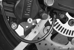
- Clear the sensor lead and connector from the clamps [A].
- Disconnect the front wheel rotation sensor lead connector [B].
- Remove the clamp bolt [C], and open the clamp.
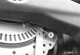
- Clear the sensor lead from the clamps [A].
- Remove the clamp bolt [B], and open the clamp.
- Remove:
Bolt [C]
Front Wheel Rotation Sensor [D]
Front Wheel Rotation Sensor Installation
- Installation is the reverse of removal.
- Run the lead correctly (see Cable, Wire, and Hose Routing section in the Appendix chapter).
Rear Wheel Rotation Sensor Removal
NOTICE The wheel rotation sensor should be handled carefully, never struck sharply, as with a hammer, or allowed to fall on a hard surface since the wheel rotation sensor is precision made. Be careful not to get water or mud on the wheel rotation sensor.
Do not try to disassemble or repair the wheel rotation sensor.
- Remove the right side fairing (see Side Fairing Removal in the Frame chapter).
- Disconnect the rear wheel rotation sensor lead connector [A].
- Clear the sensor lead and connector from the clamps [B].
- Remove the bands [C].
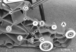
- Remove the sub frame [A] (see Rear Wheel Removal in the Wheels/Tires chapter).
- Open the clamp [B].
- Remove:
Bolts [C]
Cover [D]
Rear Wheel Rotation Sensor [E]
Rear Wheel Rotation Sensor Installation
- Installation is the reverse of removal.
- Run the lead correctly (see Cable, Wire, and Hose Routing section in the Appendix chapter).
Wheel Rotation Sensor Inspection
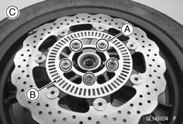
- Remove the front wheel rotation sensor [A] from the front fork (see Front Wheel Rotation Sensor Removal).
- Remove the sub frame to inspect the rear wheel rotation sensor [B] (see Rear Wheel Removal in the Wheels/Tires chapter).
- Visually inspect the wheel rotation sensors.
Replace the wheel rotation sensor if it is cracked, bent, or otherwise damaged.
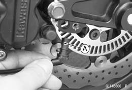
Wheel Rotation Sensor Air Gap Inspection
- Raise the front/rear wheel off the ground (see Front/Rear Wheel Removal in the Wheels/Tires chapter).
- Measure the air gap between the sensor and sensor rotor at several
points by turning the wheel slowly.
Thickness Gauge [A]
Air Gap
Standard:
Front 0.4 - 1.2 mm (0.02 - 0.05 in.)
Rear 0.4 - 1.2 mm (0.02 - 0.05 in.)
NOTE
- The sensor air gap cannot be adjusted.
If the air gap is not within the specification, inspect the hub bearing (see Hub Bearing Inspection in the Wheels/Tires chapter), sensor installation condition and sensor (see Wheel Rotation Sensor Inspection).
Wheel Rotation Sensor Rotor Inspection
- Remove:
Wheels (see Front/Rear Wheel Removal in the Wheels/Tires chapter)
Brake Disc Mounting Bolts [A]
Sensor Rotor [B]
Front Wheel [C]
Rear Wheel [D]
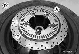
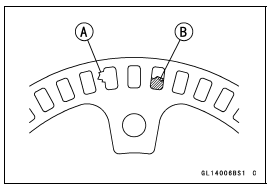
- Visually inspect the wheel rotation sensor rotor.
If the rotor is deformed or damaged (chipped teeth [A]), replace the sensor rotor with a new one.
If there is iron or other magnetic deposits [B], remove the deposits.
ABS Solenoid Valve Relay Fuse (25 A) Removal
- Refer to the Fuse Box Fuse Removal in the Electrical System chapter.
ABS Motor Relay Fuse (40 A) Removal
- Refer to the Fuse Box Fuse Removal in the Electrical System chapter.
Fuse Installation
- If a fuse fails during operation, inspect the electrical system to determine the cause, and then replace it with a new fuse of proper amperage (see Fuse Installation in the Electrical System chapter).
Fuse Inspection
- Remove the fuses (see ABS Solenoid Valve Relay Fuse (25 A)/ABS Motor Relay Fuse (40 A) Removal).
- Refer to the Fuse Inspection in the Electrical System chapter.
See also:
 Kawasaki J300 - Service manual > ABS Servicing Precautions
There are a number of important precautions that should be followed servicing the ABS system. This ABS system is designed to be used with a 12 V sealed battery as its power source. Do not use any other battery except for a 12 V sealed battery as a power source. Do not reverse the battery cable connections. This will damage the ABS hydraulic unit. To prevent damage to the ABS parts, do not disconnect the battery cables or any other electrical connections when the ignition switch is on or while the engine is running. Take care not to short the leads that are directly connected to the battery positive (+) terminal to the chassis ground. Do not turn the ignition switch on while any of the ABS electrical connectors are disconnected. Do not spray water on the electrical parts, ABS parts, connectors, leads and wiring. If a transceiver is installed on the motorcycle, make sure that the operation of the ABS system is not influenced by electric wave radiated from the antenna. Locate the antenna as far as possible away from the ABS hydraulic unit. Whenever the ABS electrical connections are to be disconnected, first turn off the ignition switch. The ABS parts should never be struck sharply, as with a hammer, or allowed to fall on a hard surface. Such a shock to the parts can damage them. The ABS parts cannot be disassembled. Even if a fault is found, do not try to disassemble and repair the ABS parts, replace it. The ABS has many brake lines, pipes, and leads. And the ABS cannot detect problems with the conventional braking system (brake disc wear, unevenly worn brake pad, and other mechanical faults). To prevent trouble, check the brake lines and pipes for correct routing and connection, the wiring for correct routing, and the brakes for proper braking power. Be sure to check for fluid leakage, and bleed the brake line thoroughly.
Kawasaki J300 - Service manual > Suspension
Exploded View