 Kawasaki J300 - Service manual > Suspension
Exploded View
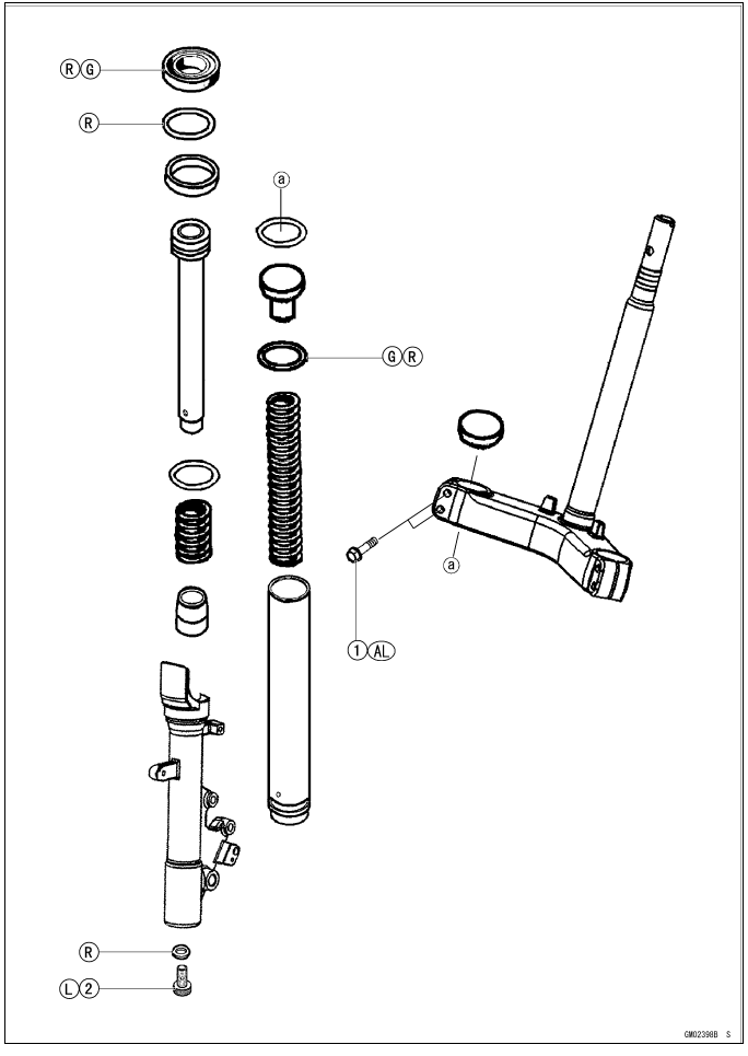
AL: Tighten the two clamp bolts alternately two times to ensure even
tightening torque.
G: Apply grease.
L: Apply a non-permanent locking agent.
R: Replacement Parts
R: Replacement Parts
Specifications
Special Tools
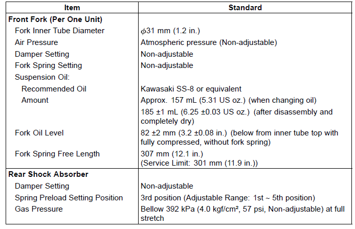
Fork Cylinder Holder Handle: 57001-183
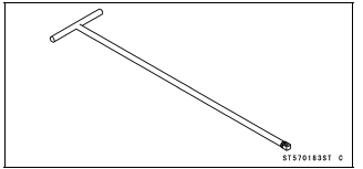
Fork Oil Level Gauge: 57001-1290
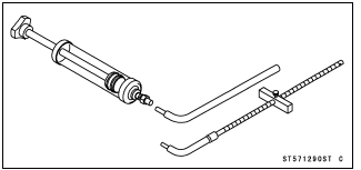
Bearing Driver Set: 57001-1129
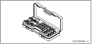
Oil Seal & Bearing Remover: 57001-Y024
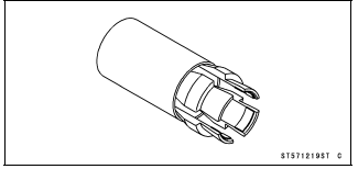
Front Fork Oil Seal Driver: 57001-1219
Front Fork
Front Fork Removal (Each Fork Leg)
- Remove:
Front Fairing (see Front Fairing Removal in the Frame chapter)
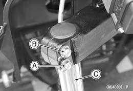
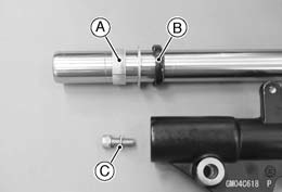
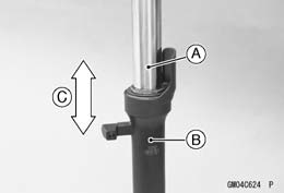
Front Wheel (see Front Wheel Removal in the Wheel/Tires chapter) - Loosen the front fork clamp bolt [A].
- Remove the front fork clamp bolt [B] retaining the front fork.
- Remove the front fork [C].
Front Fork Installation (Each Fork Leg)
- Install the front fork [A].
- Install the front fork clamp bolt [B] through the dent [C] of the front fork.
- Tighten:
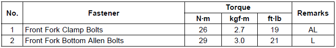
Torque - Front Fork Clamp Bolts: 26 N*m (2.7 kgf*m, 19 ft*lb)
NOTE
- Tighten the two clamp bolts alternately two times to ensure even tightening torque.
- Install the removed parts (see appropriate chapters).
Front Fork Oil Change
- Remove:
Front Fairing (see Front Fairing Removal in the Frame chapter)
Front Wheel (see Front Wheel Removal in the Wheel/Tires chapter)
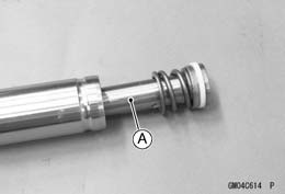
Cap [A]
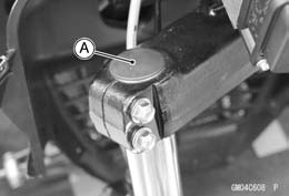
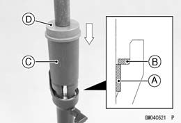
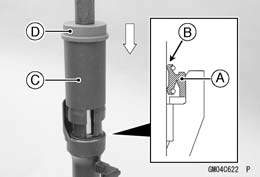
- Push the top plug [A] down with a suitable tool [B].
- Remove the retaining ring [C].

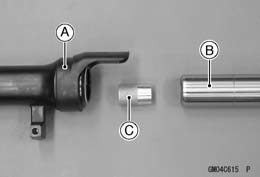
- Remove:
Front Fork (see Front Fork Removal (Each Fork Leg) )
Top Plug [A]
Fork Spring [B]
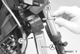
- Drain the fork oil into a suitable container [A].
- Pump the outer tube up and down at least ten times to expel the oil from the fork.
NOTE
- Pump the outer tube slowly. If the outer tube is pumped quickly, the fork oil may be spattered outward.
- Hold the fork tube upright, press the inner tube.
- Pour in the type and amount of fork oil specified.
Suspension Oil
Recommended Oil:
Kawasaki SS-8 or equivalent
Amount (Per Side):
When changing oil:
Approx. 157 mL (5.31 US oz.)
After disassembly and completely dry:
185 +-1 mL (6.25 +-0.03 US oz.)
- Measure the oil level as follows.
- Hold the outer tube vertically in a vise.
- Pump the inner tube several times to expel air bubbles.
NOTE
- Pump the outer tube slowly. If the outer tube is pumped quickly, the fork oil may be spattered outward.
- Wait until the oil level settles.
- With the fork fully compressed, insert a tape measure or rod into the inner tube, and measure the distance from the top of the inner tube to the oil.
Oil Level (fully compressed without spring)
Standard: 82 +-0.2 mm (3.2 +-0.08 in.)
If the oil is above or below the specified level, remove or add oil and recheck the oil level.
NOTE
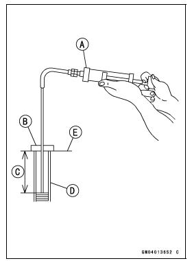
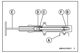
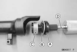
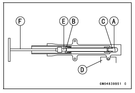
- Fork oil level may also be measured using the fork oil level gauge [A] as follows.
Special Tool - Fork Oil Level Gauge: 57001-1290
- Set the oil gauge stopper [B] so that its lower side shows the oil level distance specified [C].
- Insert the gauge tube into the inner tube [D] and position the stopper across the inner tube top end [E].
- Pull the handle slowly to draw out the excess oil until no more oil
comes up the tube.
If no oil is drawn out, there is not enough oil in the inner tube. Pour in some more oil, then draw out the excess.
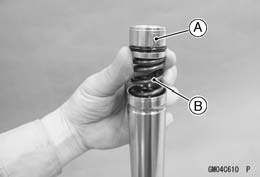
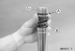
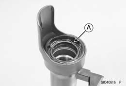
- Install the fork spring [A] so that the closed coil end [B] faces downward [C].
- Replace the O-ring [A] with a new one.
- Install:
Fork Spring [B]
Top Plug [C] with new O-ring
Front Fork (see Front Fork Installation (Each Fork Leg) )
- Install the front fork to the stem base temporary (see Front Fork Installation (Each Fork Leg) ).
- Push the top plug [A] down with a suitable tool [B].
- Install the new retaining ring [C].
- Tighten:
Torque - Front Fork Clamp Bolts: 26 N*m (2.7 kgf*m, 19 ft*lb)
NOTE
- Tighten the two clamp bolts alternately two times to ensure even tightening torque.
- Install the removed parts (see appropriate chapters).
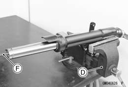
Front Fork Disassembly
- Remove the front fork and drain the fork oil (see Front Fork Oil Change).
- Hold the fork leg horizontally in a vise [A].
- Loosen the front fork bottom Allen bolt [B] while holding the cylinder
unit [C] with a commercially available 19 mm Allen socket [D] and fork
cylinder holder handle [E].
Special Tool - Fork Cylinder Holder Handle: 57001-183
- Remove the front fork bottom Allen bolt and gasket [F].

- Remove the cylinder unit [A].
- Separate the outer tube [A] and the inner tube [B].
- Remove the cylinder base [C].
- Remove the retaining ring [A] from the outer tube.
- Remove the oil seal [A], washer [B] and bushing [C] as a set.
Special Tool - Oil Seal & Bearing Remover [D]: 57001-Y024
Front Fork Assembly
- Replace the following parts with new ones.
Bushing [A]
Oil Seal [B]
Bottom Allen Bolt Gasket [C]
- Install the cylinder unit [A] to the inner tube.
- When the spring [B] is removed, install it so that the large diameter [C] of the spring faces downward.
If the collar [D] is damaged, replace it with a new one.
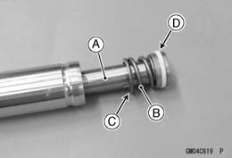
- Install the cylinder base [A] to the cylinder unit [B].
- Install the inner tube to the outer tube.
- Apply a non-permanent locking agent to the threads of the front fork bottom Allen bolt [A] and screw it to the cylinder unit [B] with the new gasket [C].
- Hold the front fork horizontally in a vise [D].
- Tighten the front fork bottom Allen bolt while holding the cylinder unit
with a commercially available 19 mm. Allen socket [E] and fork cylinder
holder handle [F].
Special Tool - Fork Cylinder Holder Handle: 57001-183
Torque - Front Fork Bottom Allen Bolt: 29 N*m (3.0 kgf*m, 21 ft*lb)
- Install the new bushing [A] and washer [B] into the outer tube using the
special tools, until the washer is bottomed.
- Hold the front fork oil seal driver [C], and press it with bearing driver [D] to prevent damage to the outer tube.
Special Tools -
Bearing Driver Set: 57001-1129
Front Fork Oil Seal Driver: 57001-1219
- Apply grease to the oil seal lips, and install the oil seal [A] to the inner tube from the top.
- Install the oil seal into the outer tube using the special tools until
the oil seal is bottomed.
- Install the oil seal with its lip side [B] facing up.
- Hold the front fork oil seal driver [C], and press it with bearing driver [D] to prevent damage to the outer tube and the oil seal.
Special Tools -
Bearing Driver Set: 57001-1129
Front Fork Oil Seal Driver: 57001-1219
- Install the retaining ring.
- Pour in the specified type of oil (see Front Fork Oil Change).
Inner Tube, Outer Tube Inspection
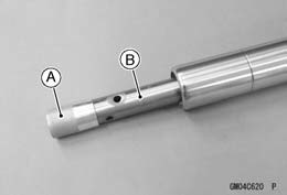
- Visually inspect the inner tube [A].
If there is any damage, replace the inner tube. Since damage to the inner tube damages the oil seal and dust seal, replace the oil seal and dust seal whenever the inner tube is replaced.
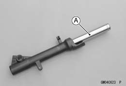
NOTICE If the inner tube is badly bent or creased, replace it. Excessive bending, followed by subsequent straightening, can weaken the inner tube.
- Temporarily assemble the inner [A] and outer [B] tubes, and pump [C]
them back and forth manually to check for smooth operation.
If you feel binding or catching, the inner and outer tubes must be replaced.
WARNING A straightened inner or outer fork tube may fall in use, possibly causing an accident resulting in serious injury or death. Replace a badly bent or damaged inner or outer tube and inspect the other tube carefully before reusing it.
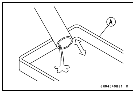
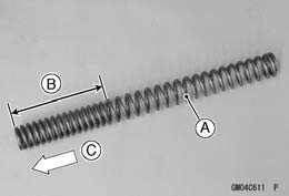
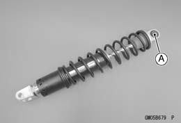
Spring Tension Inspection
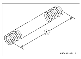
- Since a spring becomes shorter as it weakens, check its free length [A]
to determine its condition.
If the spring of either fork leg is shorter than the service limit, it must be replaced. If the length of a replacement spring and that of the remaining spring vary greatly, the remaining spring should also be replaced in order to keep the fork legs balanced for motorcycle stability.
Fork Spring Free Length
Standard: 307 mm (12.1 in.)
Service Limit: 301 mm (11.9 in.)
Rear Shock Absorber
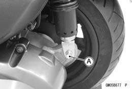
Spring Preload Adjustment
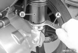
- Set the motorcycle up on its center stand.
- Using the hook wrench [A], turn the adjuster [B] to adjust the spring preload.
Spring Preload Setting
Standard Position: 3rd position
Adjustable Range: 1st - 5th position
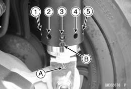
NOTICE Always adjust the spring preload adjuster in sequence (1 → 2 → 3 → 4 → 5 or 5 → 4 → 3 → 2 → 1).
Attempting to adjust directly from 1 to 5 or 5 to 1 may damage the shock absorber.
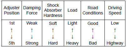
If the compression of the spring is not suited to the operating conditions, adjust it to an appropriate position by referring to the table below.
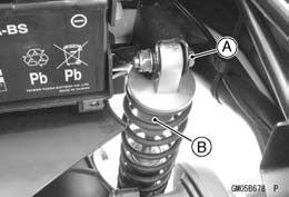
Mark [A]
"3" (3rd position) [B]
Spring Preload Adjustment
WARNING If both adjusters are not adjusted equally, handling may be impaired and a hazardous condition may result. Be sure the adjusters are set equally.
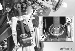
Rear Shock Absorber Removal
- Set the motorcycle up on its center stand.
- Remove:
Storage Box (see Storage Box Removal in the Frame chapter)
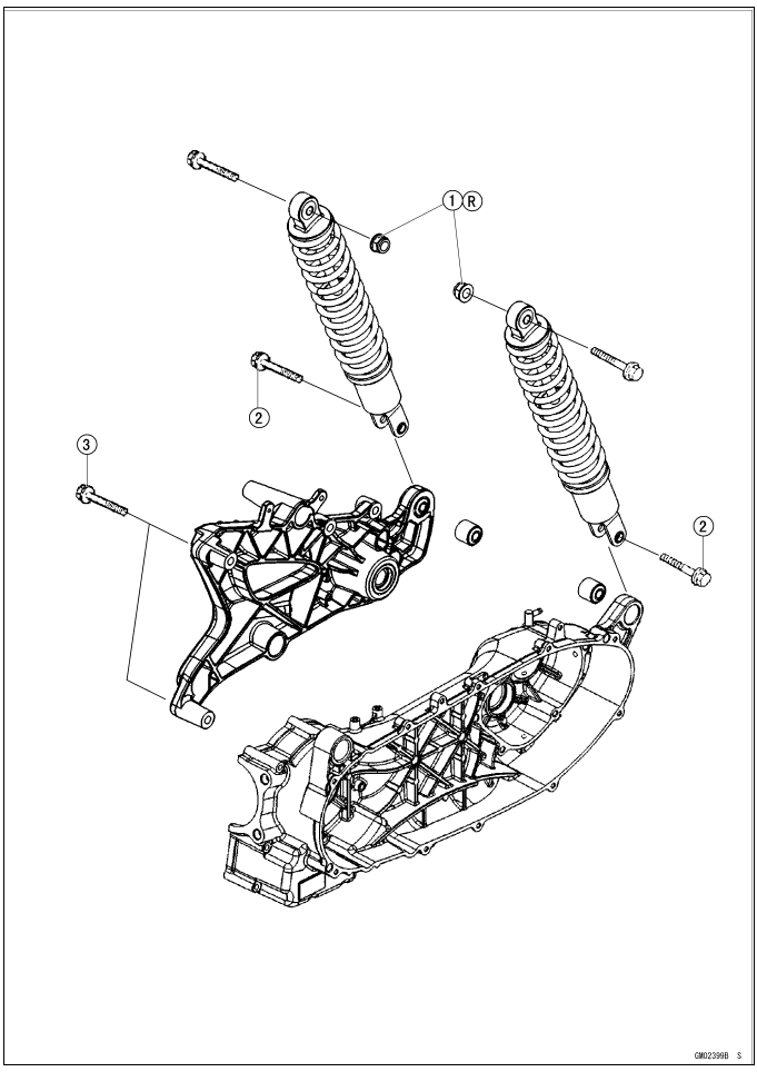
Lower Rear Shock Absorber Bolt [A]
- Remove:
Upper Rear Shock Absorber Bolt [A] and Nut
Rear Shock Absorber [B]- Remove the right rear shock absorber in the same way.
Rear Shock Absorber Installation
- Replace the upper rear shock absorber nut with a new one.
- Install the rear shock absorber.
- Tighten:
Torque -
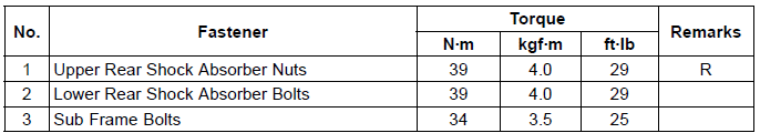
Upper Rear Shock Absorber Nut: 39 N*m (4.0 kgf*m, 29 ft*lb)
Lower Rear Shock Absorber Bolt: 39 N*m (4.0 kgf*m, 29 ft*lb)
- Install the storage box (see Storage Box Installation in the Frame chapter).
Rear Shock Absorber Inspection
- Remove the rear shock absorber (see Rear Shock Absorber Removal).
- Visually inspect the following items.
Oil Leakage
Crack or Dent
Bushing [A]
If there is any damage to the rear shock absorber replace it.
NOTE
- When replacing one shock absorber of a pair, the performance of shock absorber on the other side may be different compared to the new one due to normal wear and tear.
- After replacing the shock absorber on one side with a new one, if there is any difference in performance or feeling between the shock absorbers during riding, also replace the shock absorber on the other side.
Rear Shock Absorber Scrapping
WARNING Pressurized nitrogen may explode when heated.
The rear shock contains nitrogen gas. To avoid an explosion, do not incinerate the shock body without first releasing the nitrogen.
- Remove the rear shock absorber (see Rear Shock Absorber Removal).
- Drill the hole [A] of the reservoir tank using about 2 mm (0.08 in.) drillbit.

WARNING Pressurized gas can cause injury. Do not point the drill toward your face or body.
See also:
 Kawasaki J300 - Service manual > ABS Hydraulic Unit Removal/Installation
ABS Hydraulic Unit Removal NOTICE The ABS hydraulic unit [A] has been adjusted and set with precision at the factory. Therefore, it should be handled carefully, never struck sharply, as with a hammer, or allowed to fall on a hard surface.
Kawasaki J300 - Service manual > Steering
Exploded View