 Kymco XCITING 500 - Service Manual > Carburetor
REMOVAL
Remove the luggage box.
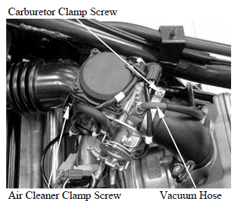
Loosen the air cleaner clamp screw.
Loosen the carburetor clamp screw.
Disconnect the vacuum hose from the carburetor.
Pull the carburetor out from the air cleaner and intake manifold.
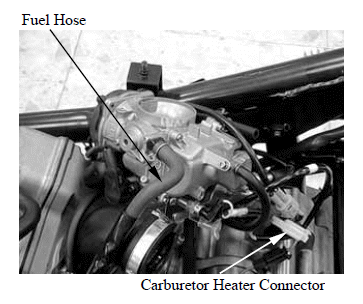
Disconnect the fuel hose from the carburetor.
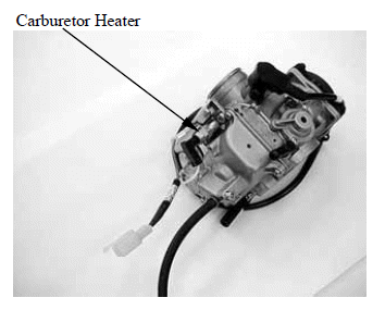
Disconnect the carburetor heater connector.
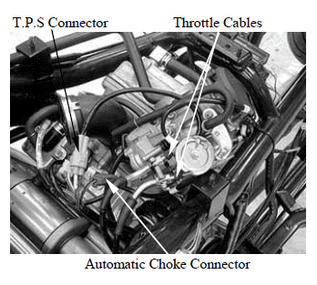
Disconnect the throttle cables.
Disconnect the automatic choke connector.
Disconnect the T.P.S connector.
Remove the carburetor.
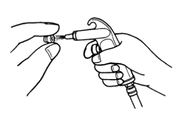
DISASSEMBLY
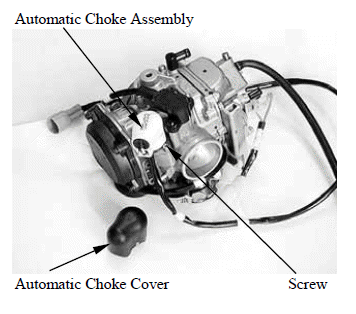
With the automatic choke cover removed, remove the screw and automatic choke assembly.
The automatic choke assembly is a non-disassemblable type
Remove the carburetor heater.
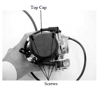
Remove the four screws and top cap.
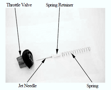
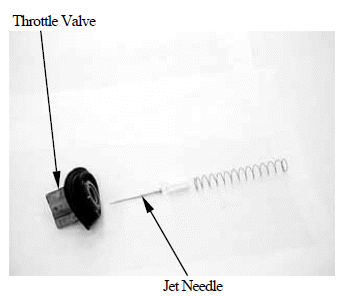
Remove the spring , spring retainer, jet needle and throttle valve.
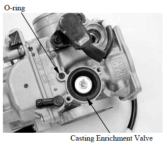
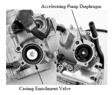
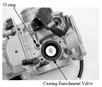
Remove the two screws and casting enrichment valve cover and then take out the spring.
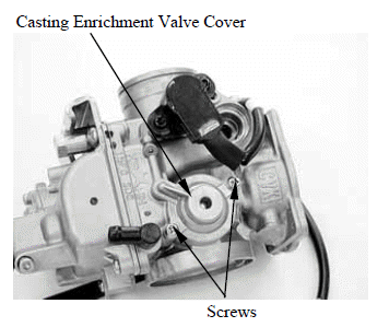
Remove the casting enrichment valve and O-ring.
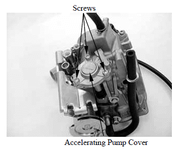
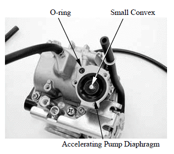
Remove the three screws and accelerating pump cover.
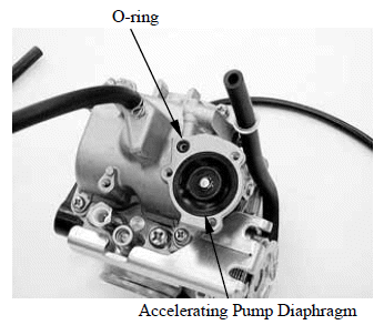
Remove the accelerating pump diaphragm and O-ring.
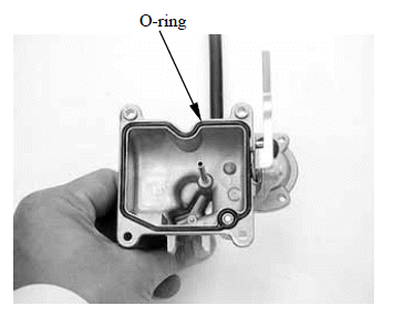
Remove the four screws and float chamber.
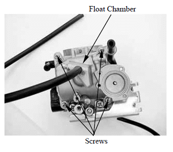
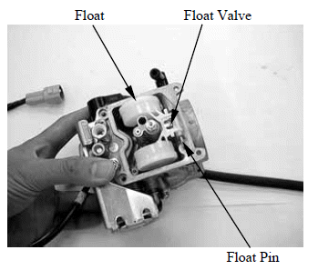
Pull float pin outs, then remove the float and float valve.
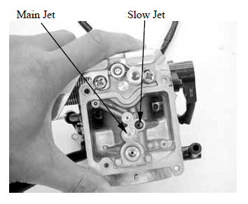
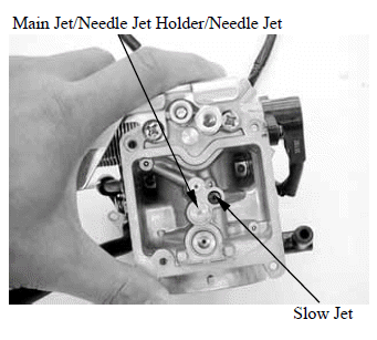
Remove the slow jet.
Remove the main jet.
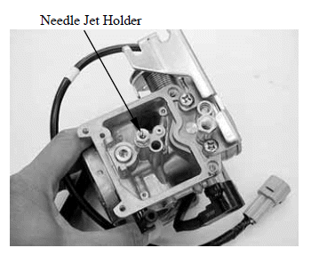
Remove the needle jet holder.
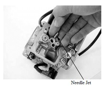
Remove the needle jet.
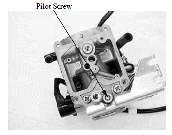
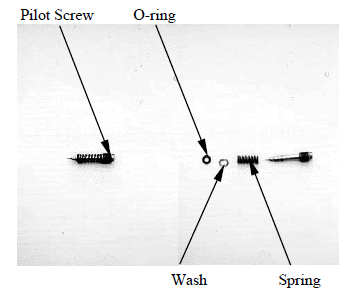
Remove the pilot screw, spring, washer and O-ring.
Before pilot screw removal, slowly turn the pilot screw clockwise and count the number of turns until the screw is lightly seated. Make a note of how many turns were made so the screw can be reset correctly.
FLOAT/FLOAT VALVE INSPECTION
Inspect the float for deformation or damage.
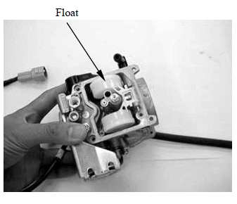
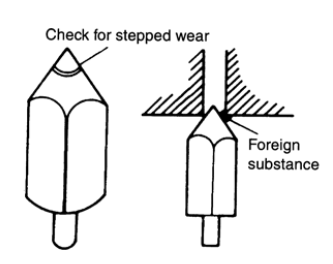
Check the float valve and valve seat for foreign substance, clogging or damage.
Check the tip of the float valve, where it contacts the valve seat, for stepped wear or contamination.
Check the operation of the float valve.
CARBURETOR BODY/JETS INSPECTION AND CLEANING
Check carburetor body and each jet for wear or damage.
Clean all jets with a spray-type carburetor cleaner and dry them using compressed air.
Clean all circuits of the carburetor thoroughly-not just the perceived problem area. Clean the circuits in the carburetor body with a spray-type cleaner and allow each circuit to soak, if necessary, to loosen dirt and varnish. Blow the body dry using compressed air.
- Some carburetor cleaning chemicals , especially dip type soaking solutions, are very corrosive and must be handled carefully. Always follow the chemical manufacturer's instructions on proper use, handling and storage.
- Do not use a wire to clean the jets or passageways. A wire can damage the jets and passageways. If the components cannot be cleaned with a spray cleaner it may be necessary to use a dip-type cleaning solution and allow them to soak. Always follow the chemical manufacturer's instructions for proper use and cleaning of the carburetor components.
PILOT SCREW INSPECTION
Remove the O-ring from the pilot screw.
Check the pilot screw for wear or damage.
The pilot screw is factory pre-set and should not be removed unless the carburetor is overhauled.
Damage to the pilot screw is tightened against the seat.
THROTTLE VALVE/JET NEEDLE INSPECTION
Check the throttle valve and jet needle for scratches, wear or damage.
CASTING ENRICHMENT VALVE/ACCELERATING PUMP DIAPHRAGM INSPECTION
Check the casting enrichment valve/accelerating pump diaphragm for damage and clogging.
If any abnormal condition is found, wash the part clean. If damage or clogging is found, replace the part with a new one.
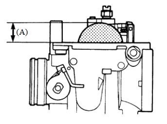
FLOAT LEVEL INSPECTION
Check the float level after checking the float valve, valve seat and float.
Set the carburetor so that the float valve end just contacts the float arm lip. Make sure the float valve tip is securely in contact with the valve seat.
Measure the float level with the float level gauge.
Float level (A): 18.5mm (0.74 in)
The float level cannot be adjusted.
Replace the float assembly if the float level is out of specification.
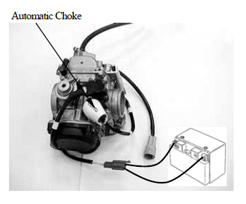
AUTO-BYSTARTER INSPECTION
Disconnect the connector.
Remove the automatic choke cover.
Connect the positive (+) terminal of a 12 V battery to Yellow lead and the negative (-) terminal to the other Yellow lead.
Check that the automatic choke section is heated in 5 minutes after the battery has been connected.
To inspect the function, check for change of temperature from the cold condition.
Do not attempt to disassemble the automatic choke for the purpose of checking temperature.
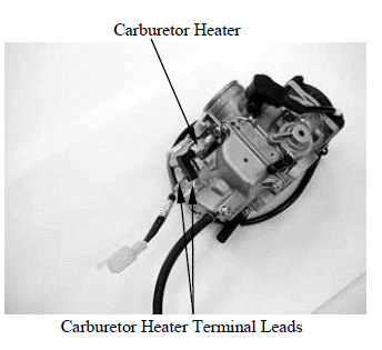
CARBURETOR HEATER INSPECTION
Disconnect the carburetor heater terminal leads.
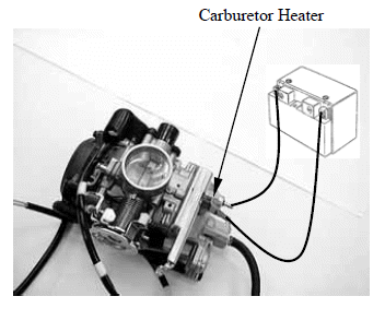
Connect the positive (+) terminal of a 12 V battery to the terminal of the carburetor heater and the battery negative (-) terminal to the terminal.
Check that the heater section is heated in 5 minutes after the battery has been connected.
REASSEMBLY
Carburetor reassembly can be performed in the reverse order of disassembly. When reassembling, carefully observe the following instructions.
- Assemble the parts taking consideration of their function.
- Replace O-rings and seals with new ones.
Fit a new O-ring in to the float chamber groove securely.
Assemble the accelerating pump diaphragm and new O-ring.
Install the accelerating pump diaphragm with the small convex facing up.
Assemble the coasting enrichment valve and new O-ring.
Assemble the jet needle, spring retainer, spring and throttle valve.
Apply thermo-grease to the threads and tighten the carburetor heater securely.
After cleaning, reinstall the pilot screw to the original setting by turn the screw in until it lightly seats, and then backing it out the same number of turns counted during disassembly.
Replace the O-ring with a new one.
After the assembly and installation on the engine have been completed, perform the following adjustment.
Throttle cable adjustment.
Idle speed adjustment.
INSTALLATION
Installation is in the reverse order of removal.
See also:
 Kymco XCITING 500 - Service Manual > Schematic Drawing
FUEL SYSTEM The fuel pump is operated by an electromagnetic force and its electrical energy is supplied from the battery. The fuel sent under pressure by the fuel pump flows into the float chamber when the float of the carburetor has dropped and the needle valve is open. When the needle valve closes, the pressure of the fuel in the hose connecting the carburetor and the fuel pump increases, and when the set pressure is reached, the operation of the fuel pump is stopped by the fuel pressure to prevent excessive supply.
Kymco XCITING 500 - Service Manual > Fuel Filter/Fuel Pump
FUEL FILTER INSPECTION Visually check the fuel filter. If accumulation of sediment or clogging is found, replace the fuel filter with a new one. Install the fuel filter with the arrow mark facing forward.