 Kymco XCITING 500 - Service Manual > Clutch/driven Pulley
REMOVAL
Remove the left crankcase cover.
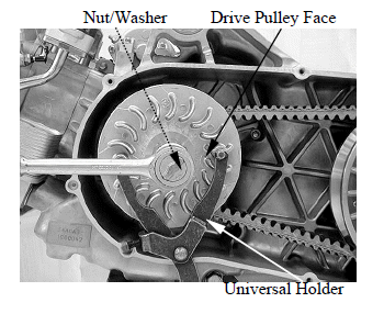
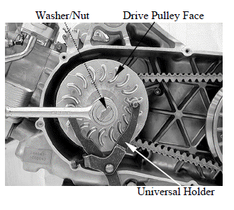
Hold the drive pulley face with the special tool and loosen the drive pulley face nut.
Special tool: Universal holder E017
Remove the nut, washer and drive pulley face.
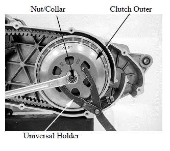
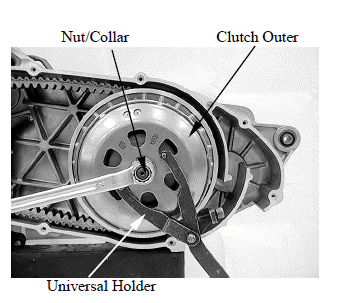
Hold the clutch outer with the special tool as shown.
Special tool: Universal holder E017
Remove the nut, collar and clutch outer.
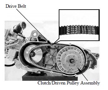
Remove the clutch/driven pulley assembly and drive belt.
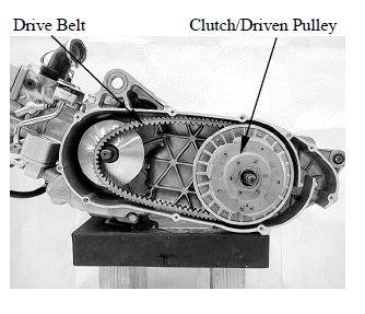
DISASSEMBLY
Clutch/Driven Pulley
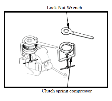
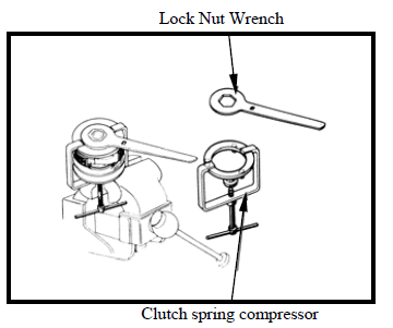
Hold the clutch/driven pulley assembly with the clutch spring compressor.
Be sure to use a clutch spring compressor to avoid spring damage.
Special tool: Clutch Spring Compressor E053
Set the tool in a vise and remove the clutch drive plate nut.
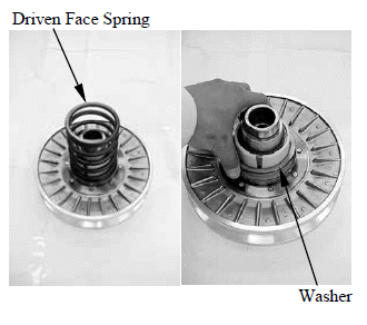
Remove the spring compressor and disassemble the following:
- Clutch assembly
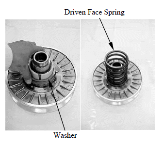
- Driven face spring
- Driven pulley
Remove the washer
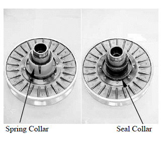
Remove the spring collar.
Remove the seal collar.
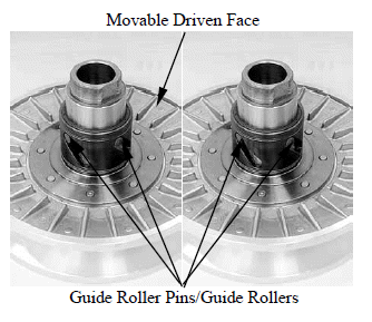
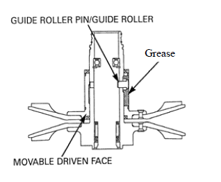
Remove the guide roller pins, guide rollers and the movable driven face.
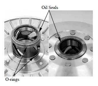
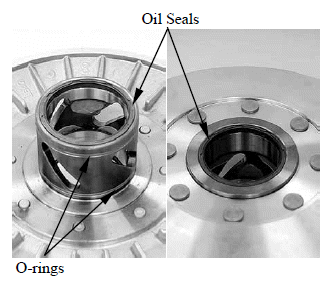
Remove the O-rings and oil seals from the movable driven face.
Driven Face Bearing Replacement
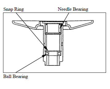
Remove the driven face needle bearing.
Remove the snap ring, then remove the ball bearing.
Apply grease to new ball bearing.
Install the ball bearing into the driven face.
Install the snap ring to groove in the driven face securely.
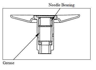
Filling 25 g of grease to the driven face inner surface.
Apply grease to new needle bearing.
Press the needle bearing into the driven.
INSPECTION
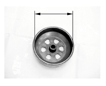
Clutch Outer
Check the clutch outer for wear or damage.
Measure the clutch outer I.D..
Service limit: 160.5 mm (6.32 in)
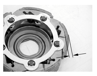
Clutch Shoe Lining
Check the clutch shoe for wear or damage.
Measure the thickness of each shoe.
Service limit: 1 mm (0.04 in)
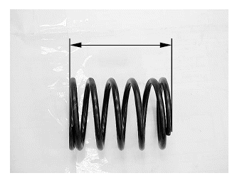
Driven Face Spring
Measure the driven face spring free length.
Service limit: 100.7 mm (4.028 in)
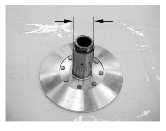
Driven Face
Check the driven face for scratches, scoring or damage.
Measure the driven face boss O.D..
Service limit: 47.94 mm (1.887 in)
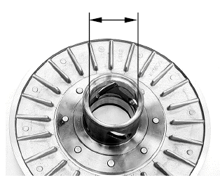
Movable Driven Face
Check the movable driven face for scratches, scoring or damage.
Check the guide grooves for stepped wear or damage.
Measure the movable driven face I.D..
Service limit: 48.06 mm (1.892 in)
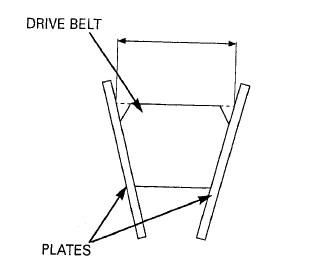
Drive Belt
Check the drive belt for cracks, separation or abnormal or excessive wear.
Attach the suitable plates ad shown.
Measure the drive belt width.
Service limit: 27.9 mm (1.116 in)
Remove the clutch/driven pulley, then replace the drive belt if necessary.
ASSEMBLY
Clean any oil from the drive belt sliding surfaces on the driven face.
Apply grease to new oil seal lips and install into the movable driven face.
Coat new O-rings with grease and install them into the movable driven face grooves.
Install the movable driven face onto the driven face.
Install the guide rollers and guide roller pins.
Filling 8 g of grease to each guide groove.
Install the seal collar.
Install spring collar.
Install washer.
Install driven face spring.
Install the drive belt into the driven pulley.
Squeeze and hold the drive belt your hand.
Set the clutch spring compressor over the clutch/driven pulley assembly and hold the spring compressor in a vice.
Special tool: Clutch Spring Compressor E053
Compress the driven face spring.
Install and tighten the clutch drive plate nut to the specified torque.
Torque: 78 N*m (7.8 kgf*m, 56 lbf*ft)
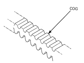
Install the drive belt with the arrow mark facing up and towards to clockwise.
Install the drive belt and clutch/driven pulley assembly.
Hold the clutch outer with the special tool as shown.
Special tool: Universal holder E017
Install the collar and nut.
Tighten the nut to the specified torque.
Torque: 80 N*m (8 kgf*m, 58 lbf*ft)
Install the drive pulley face and washer.
Apply oil to the drive pulley face nut threads and seating surface and install the nut.
Hold the drive face with the special tool and tighten the bolt to the specified torque.
Special tool: Universal holder E017
Torque: 135 N*m (13.5 kgf*m, 97 lbf*ft)
See also:
 Kymco XCITING 500 - Service Manual > Drive Pulley
REMOVAL Remove the left crankcase cover. Hold the drive pulley face with the special tool and loosen the drive pulley face nut. Special tool: Universal holder E017
Kymco XCITING 500 - Service Manual > Final Reduction
SCHEMATIC DRAWING SERVICE INFORMATION