 Kawasaki J300 - Service manual > Cylinder Head
Cylinder Compression Measurement
- Remove the left side fairing (see Side Fairing Removal in the Frame chapter).
- Warm up the engine thoroughly.
- Stop the engine.
- Remove the spark plug (see Spark Plug Replacement in the Periodic Maintenance chapter).
- Attach the compression gauge [A] and adapter [B] firmly into the spark plug hole.
Special Tools -
Compression Gauge, 20 kgf/cm²: 57001-221
Compression Gauge Adapter, M10 Ă— 1.0: 57001-1317
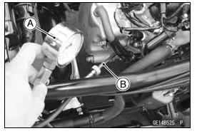
- Using the starter motor, turn the engine over with the throttle fully open until the compression gauge stops rising; the compression is the highest reading obtainable.
NOTE
- Use the battery which is fully charged.
Cylinder Compression
Usable Range: 1 370 - 1 770 kPa (14 - 18 kgf/cm², 199 - 256 psi) at 570 r/min (rpm)
- Install the spark plug (see Spark Plug Replacement in the Periodic
Maintenance chapter).
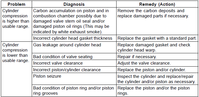
- The following table should be consulted if the obtainable compression reading is not within the usable range.
Cylinder Head Removal
- Drain the coolant (see Coolant Change in the Periodic Maintenance chapter).
- Remove:
Cylinder Head Cover (see Cylinder Head Cover Removal)
Camshaft Sprocket (see Camshaft Sprocket Removal)
Throttle Body Assy (see Throttle Body Assy Removal in the Fuel System (DFI) chapter)
Intake Manifold (see Intake Manifold Removal)
Exhaust Pipe (see Exhaust Pipe Removal)
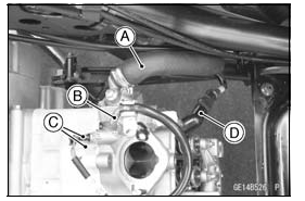
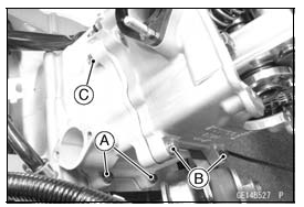
- Loosen the clamp screw and disconnect the water hose [A].
- Open the clamp and disconnect the water bypass hose [B].
- Disconnect:
Water Temperature Sensor (Meter) Connectors [C]
Spark Plug Cap [D]
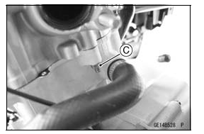
- Loosen the Cylinder Bolts [A].
- Remove:
Cylinder Head Bolts [B]
Cylinder Head Nuts (M6) [C]
- Remove:
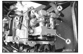
Cylinder Head Nuts (M10) [A]
Cylinder Head [B] and Gasket
Cylinder Head Installation
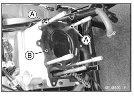
- Be sure that the two dowel pins [A] are in place on the cylinder.
- Replace the cylinder head gasket [B] with a new one.
- Install the new cylinder head gasket.
- Install the cylinder head.
- First, tighten the cylinder head nuts (M10) [A].
Torque -
Cylinder Head Nuts (M10):
First 20 N*m (2.0 kgf*m, 15 ft*lb)
Final 37 N*m (3.8 kgf*m, 27 ft*lb)
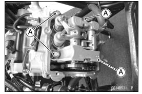
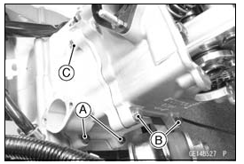
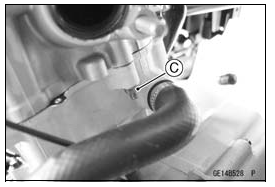
- After that, tighten the cylinder bolts [A], cylinder head bolts [B] and
cylinder head nuts (M6) [C].
Torque - Cylinder Bolts: 9.8 N*m (10 kgf*m, 87 in*lb)
Cylinder Head Bolts: 9.8 N*m(10 kgf*m, 87 in*lb)
Cylinder Head Nuts (M6): 9.8 N*m (10 kgf*m, 87 in*lb) - Install the removed parts (see appropriate chapters).
Cylinder Head Cleaning
- Remove the cylinder head (see Cylinder Head Removal).
- Remove the valves (see Valve Removal).
- Wash the head with a high flash-point solvent.
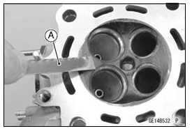
- Scrape the carbon out of the combustion chamber and exhaust port with a suitable tool [A].
- Clean the cylinder head in a bath of high flash-point solvent.
- Using compressed air, blow out any particles which may obstruct the oil passage in the cylinder head.
- Install the valves (see Valve Installation).
Cylinder Head Warp Inspection
- Clean the cylinder head (see Cylinder Head Cleaning).
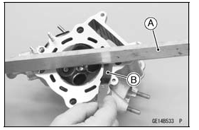
- Lay a straightedge [A] across the lower surface of the cylinder head at several positions.
- Use a thickness gauge [B] to measure the space between the straightedge and the cylinder head.
Cylinder Head Warp
Service Limit: 0.05 mm (0.002 in.)
If the cylinder head is warped more than the service limit, replace it.
If the cylinder head is warped less than the service limit, repair the head by rubbing the lower surface on emery paper secured to a surface plate (first No. 200, then No.400).
See also:
 Kawasaki J300 - Service manual > Rocker Arm, Rocker Shaft
Rocker Arm Removal Remove: Camshaft Sprocket (see Camshaft Sprocket Removal) Rocker Shaft Stopper Bolt [A] Rocker Shaft Stopper [B] Using the 5 mm (0.20 in.) bolt [A], remove the rocker shafts [B] and rocker arms [C].
 Kawasaki J300 - Service manual > Valves
Valve Clearance Inspection Refer to the Valve Clearance Inspection in the Periodic Maintenance chapter. Valve Clearance Adjustment Refer to the Valve Clearance Adjustment in the Periodic Maintenance chapter.


