 Kymco XCITING 500 - Service Manual > Oil pressure switch
CHECK
Start the engine.
Check the oil pressure indicator goes out after one or two seconds. If the oil pressure indicator stay on, stop the engine immediately and determine the cause (section 20).
OIL PRESSURE RELIEF VALVE
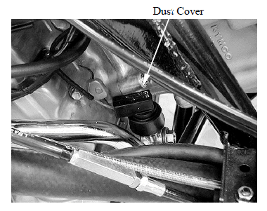
Remove the right crankcase cover.
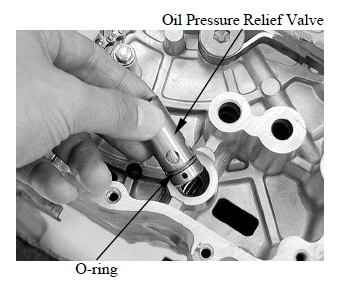
Remove the pressure relief valve and O-ring from the right crankcase.
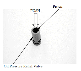
INSPECTION
Check the operation of the pressure relief valve buy pushing on the piston.
INSTALLATION
Apply oil to a new O-ring and install the pressure relief valve groove, and install the relief valve to the right crankcase.
OIL PUMP
REMOVAL
Remove the flywheel.
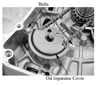
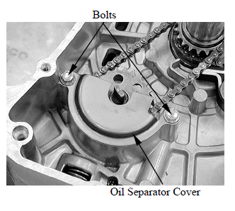
Remove the attaching bolt and oil separator cover.
When removing and installing the oil pump, use care not to allow dust or dirt to enter the engine.
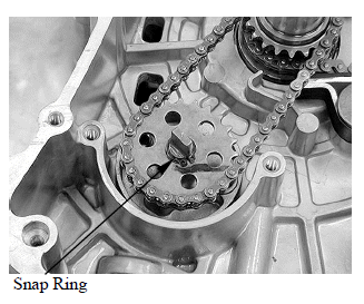
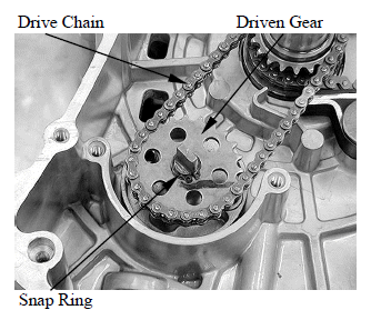
Remove snap ring.
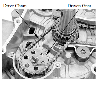
Remove the oil pump driven gear, then remove the oil pump drive chain.
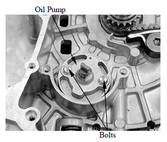
Remove the two oil pump bolts to remove the oil pump.
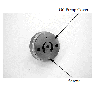
DISASSEMBLY
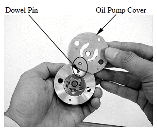
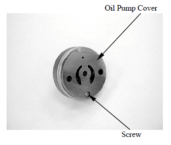
Remove the screw and oil pump cover.
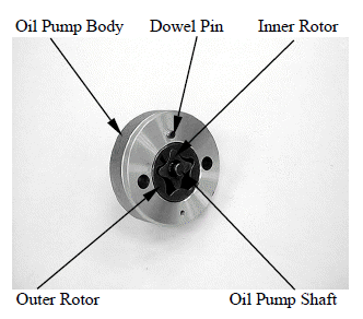
Remove the dowel pin, oil pump shaft, oil pump outer rotor and inner rotor.
INSPECTION
Temporarily install the oil pump shaft.
Install the outer and inner rotors into the oil pump body.
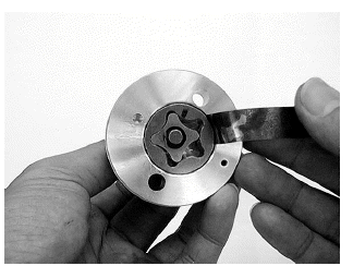
Measure the tip clearance.
Service limit: 0.2 mm (0.008 in)
Measure at several points and use the largest reading to compare the service limit.
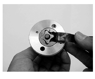
Measure the pump body clearance.
Service limit: 0.25 mm (0.01 in)
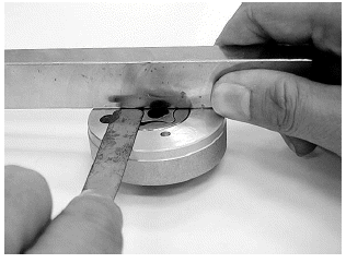
Measure the side clearance with the straight edge and feeler gauge.
Service limit: 0.12 mm (0.0048 in)
ASSEMBLY
Dip all parts in clean engine oil.
Install the outer rotor into the oil pump body.
Install the inner rotor into the outer rotor.
Install the oil pump shaft.
Install the dowel pin onto the oil pump body.
Install the oil pump cover onto the oil pump body by aligning the dowel pin.
Install and tighten the screw to the specified torque.
Torqur: 3 N*m (0.3kgf*m, 2 lbf*ft)
INSTALLATION
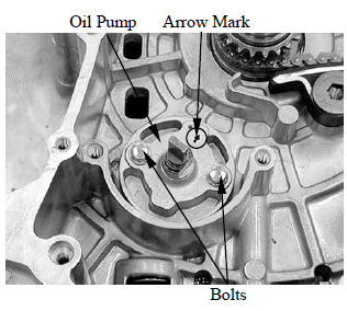
Install the oil pump and tighten the two bolts securely.
Make sure the pump shaft rotates freely and arrow on the oil pump is upside.
Install the oil pump driven sprocket and drive chain.
Install the snap ring.
Install the oil separator cover properly and tighten two bolts securely as shown.
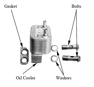
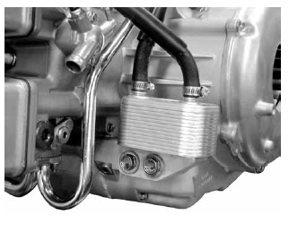
OIL COOLER
REMOVAL
Drain the engine oil and remove the oil filter cartridge.
Drain the coolant from the system.
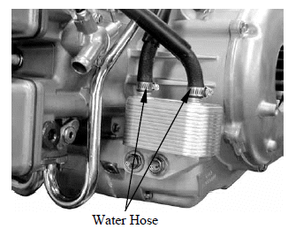
Loosen the hose bands and disconnect the oil cooler water hoses from the cooler.
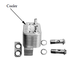
Remove the oil cooler mounting bolts, washers, oil cooler and gasket.

INSPECTION
Check the cooler for damage.
INSTALLATION
Install the gasket and oil cooler.
Install the washers and tighten the oil cooler bolts to the specified torque.
Torque: 35 N*m (3.5 kgf*m, 25 lbf*ft)
Connect the oil cooler water hoses, tighten the hose band securely.
Install the oil filter cartridge and fill the crankcase with recommended engine oil.
Fill the cooling system and bleed air.
See also:
 Kymco XCITING 500 - Service Manual > Service information
LUBRICATION SYSTEM DIAGRAM SERVICE INFORMATION