 Kymco XCITING 500 - Service Manual > Side Stand Switch
INSPECTION
Remove the left floor skirt.
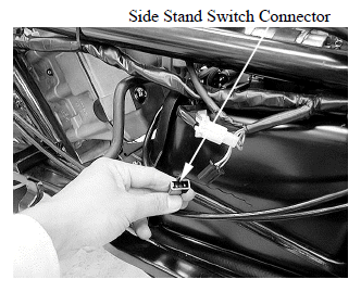
Disconnect the side stand switch connector.
There should be continuity between the Yellow/Green and Green with the side stand retracted.
There should be continuity between the Yellow/Black and Green with the side stand applied.
REMOVAL
Remove the left floor skirt.
Disconnect the side stand switch connector.
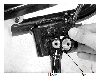
Remove the bolt and side stand switch from the side stand.
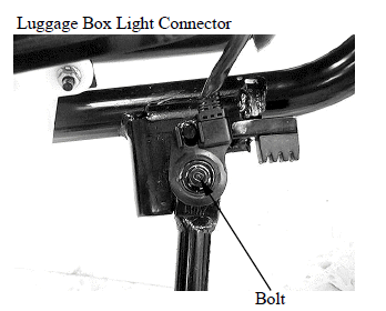
Installs the side stand switch aligning the switch pin with the side stand hole.
Install and tighten the side stand switch bolt securely.
HORN
INSPECTION
Remove the front cover.
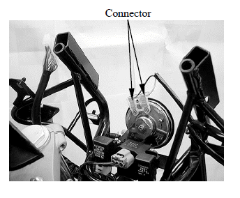
Disconnect the horn connectors from the horn.
Connect a 12 V battery to the horn terminals.
The horn is normal if it sounds when the 12 V battery is connected across the horn terminals.
REMOVAL/INSTALLATION
Remove the front cover.
Disconnect the horn connectors from the horn.
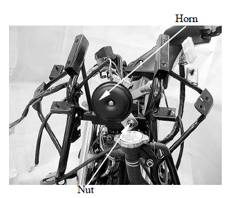
Remove the nut and horn.
Installation is in the reverse order of removal.
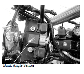
BANK ANGLE SENSOR
INSPECTION
Support the scooter level surface.
Remove the meter panel.
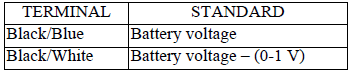
Turn the ignition switch to "ON" and measure the voltage between the following terminals of the bank angle sensor connector with the connector connected.
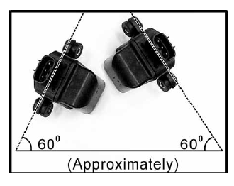
The engine should stop as you incline the bank angle sensor approximately degrees to the left or right.
REMOVAL/INSTALLATION
Disconnect the bank angle sensor connector.
Remove the two screws, washers and bank angle sensor.
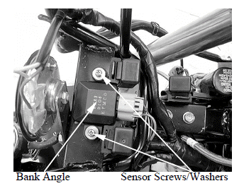
Installation is in the reverse order of removal.
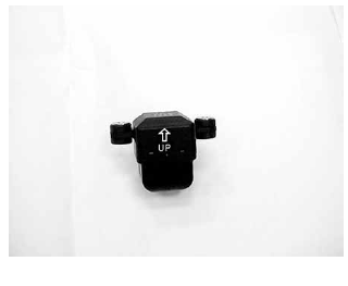
Install the bank angle sensor with its "UP" mark facing up.
Tighten the mounting screws securely.
HEATER CONTROL UNIT
INSPECTION
Heater control unit inspection
1.Open ignition switch to check if the brown /blue wire of it is enough voltage.
2.Put the heater controller unit in refrigerator. Start engine after keeping the temperature under 10 +- 4.
3.Check if the yellow wire of heater controller unit has output voltage.
Start engine and if the temperature of heater controller unit is under 10 +- 4. Check if the white/yellow wire of heater controller unit has output voltage. If it has not any voltage. It is damaged.
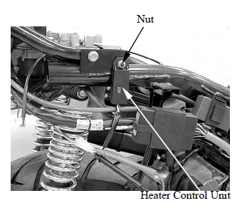
REMOVAL/INSTALLATION
Remove the side body cover.
Remove the nut and heater control unit.
Installation is in the reverse order of removal.
See also:
 Kymco XCITING 500 - Service Manual > Oil Pressure Switch
INSPECTION If the oil pressure warning indicator stays on while the engine running, check the engine oil level before inspection. Make sure that the oil pressure warning indicator come on with the ignition switch ON.