 Kymco XCITING 500 - Service Manual > Oil Pressure Switch
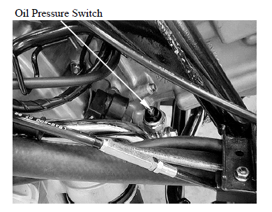
INSPECTION
If the oil pressure warning indicator stays on while the engine running, check the engine oil level before inspection.
Make sure that the oil pressure warning indicator come on with the ignition switch ON.
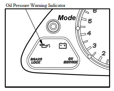
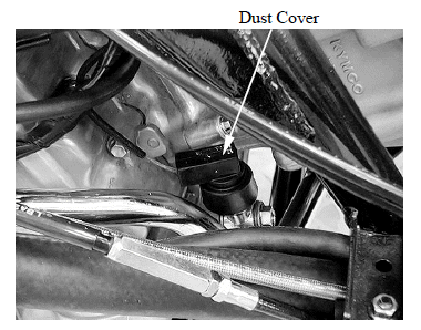
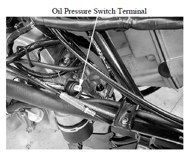
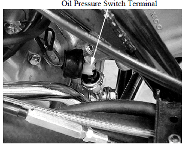
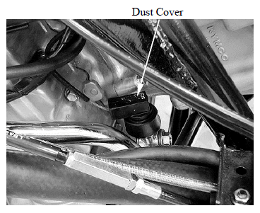
If the indicator does not come on, inspect as follow: Remove the dust cover and disconnect oil pressure switch terminal.
Short the oil pressure switch wire terminal with the ground using a jumper wire.
The oil pressure warning indicator comes on with the ignition switch is ON.
If the light does not comes on, check the fuse and wires for a loose connection or an open circuit.
Start the engine and make sure that the light goes out.
If the light does not go out, check the internal oil for leak.
If the engine oil does not leak, replace the oil pressure switch (see below).
REMOVAL/INSTALLATION
Remove the dust cover and disconnect oil pressure switch terminal.
Remove the oil pressure switch from the crankcase.
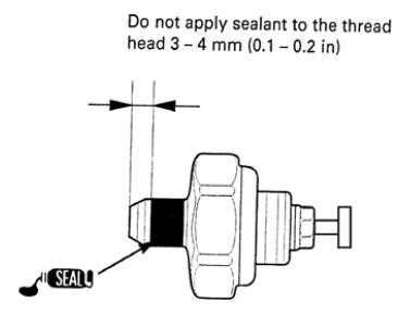
Apply sealant to the oil pressure switch threads as shown.
Install the oil pressure switch onto the crankcase, tighten it to the specified torque.
Torque: 22 N*m (2.2 kgf*m, 16 lbf*ft)
Connect the oil pressure switch terminal to the switch.
Install the dust cover.
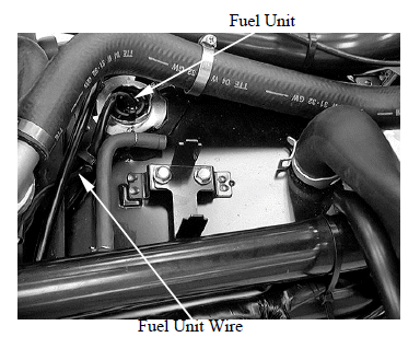
FUEL UNIT
REMOVAL
Remove the floorboard.
Disconnect the fuel unit connector.
Turn the fuel unit retainer counterclockwise and remove it.
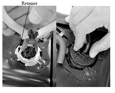
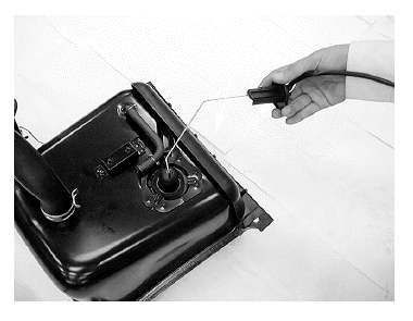
Remove the fuel unit.
Be careful not to bend or damage the fuel unit float arm.
INSPECTION
Connect the fuel unit wire connectors and turn the ignition switch "ON".
Before performing the following test, operate the turn signals to determine that the battery circuit is normal.
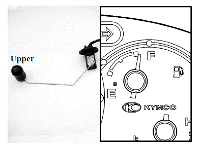
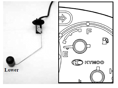
Check the fuel meter for correct indication by moving the fuel unit float up and down.
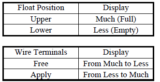
The fuel meter is normal if it operates as above indicated. If not, check for poorly connected terminals or shorted wires.
INSTALLATION
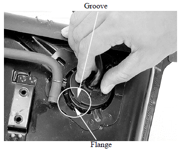
Install the O-ring and fuel unit.
Align the groove on the fuel unit with the flange on the fuel tank.
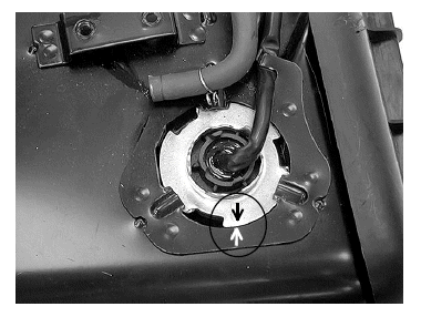
Install the fuel unit retainer.
Align the arrow mark on the fuel unit retainer with the arrow mark on the fuel tank.
See also:
 Kymco XCITING 500 - Service Manual > Brake Light Switch
Remove the upper handlebar cover. Disconnect front or rear light switch connector and check for continuity between the switch terminals. There should be continuity with the front or rear brake lever squeezed, and there should be no continuity with the front or rear brake lever is released.
Kymco XCITING 500 - Service Manual > Side Stand Switch
INSPECTION Remove the left floor skirt. Disconnect the side stand switch connector. There should be continuity between the Yellow/Green and Green with the side stand retracted.