Peugeot Satelis - Service manual > Electricity/Location of Components
Electricity/Location of Components
ELECTRICITY
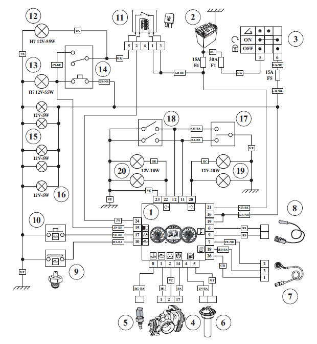
4 stroke indirect injection system functional diagram
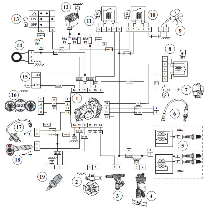
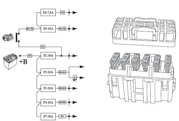
- Injection ECU.
- Engine speed and position sensor.
- Petrol injector.
- Fuel pump.
- Ignition coil.
- Lambda sensor.
- Starter motor switch.
- Starter motor relay.
- Cooling fan.
- Fan relay.
- Injection relay.
- Battery.
- Ignition switch.
- Transponder antenna.
- Diagnostic plug.
- Instrument panel.
- Kickstand switch.
- Emergency stop switch.
- Engine temperature sensor.
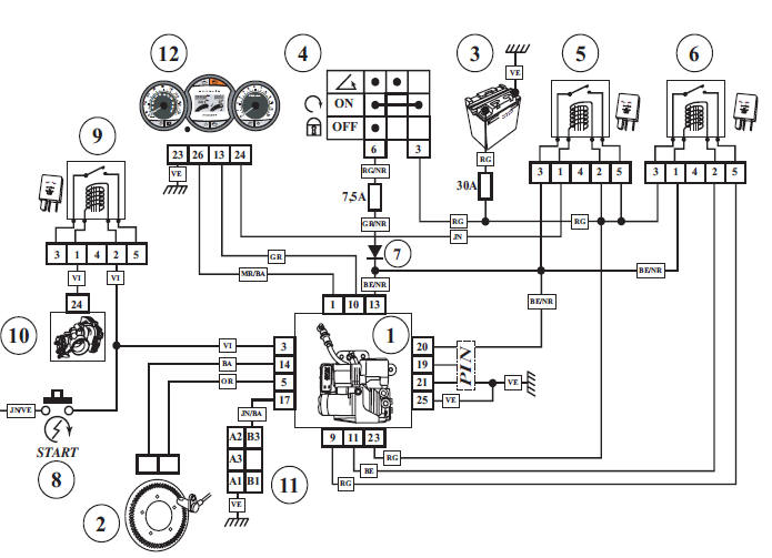
Schematic diagram of the instrument panel and of the lighting
- Instrument panel.
- Battery.
- Ignition switch.
- Immobilizer.
- Injection ECU.
- Fuel gauge.
- Speed sensor.
- Outside temperature sensor.
- Oil pressure switch.
- Saddle opening contact switch.
- Lighting relay.
- Dip beam.
- High beam.
- Dip switch (main/low headlight).
- "Side light" bulbs.
- Number plate light.
- Direction indicator switch.
- Hazard warning lights switch.
- RH direction indicators.
- LH direction indicators.
ABS/MBS system schematic diagram
- Pressure control unit.
- Speed sensor and pulse wheel.
- Battery.
- Ignition switch.
- Power supply relay.
- ABS/MBS relay.
- ABS diode.
- Starter motor switch.
- Starter motor relay.
- Injection ECU.
- Diagnostic plug.
- Instrument panel (diagnostic lamp, machine speed).
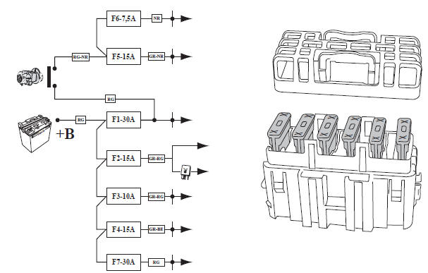
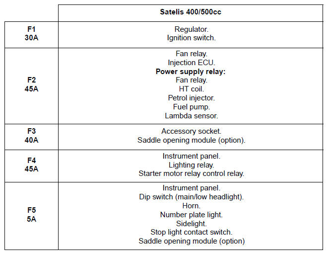
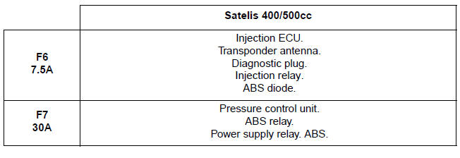
Fuses and energy distribution
LOCATION OF COMPONENTS
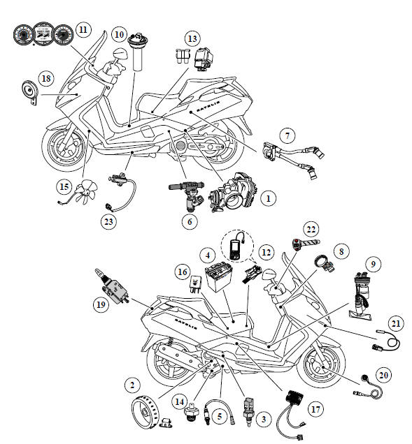
- Injection ECU.
- Engine speed and position sensor.
- Engine temperature sensor.
- Battery.
- Lambda sensor.
- Petrol injector.
- Ignition coil.
- Transponder antenna.
- Fuel pump.
- Fuel gauge.
- Diagnostic lights.
- Diagnostic plug.
- Starter motor relay/Fuses.
- Oil pressure switch.
- Motor-driven fan.
- Lighting relay/Fan relay/Power supply relay/Starter motor relay control relay/ABS relay.
- Voltage regulator.
- Horn.
- Saddle lock.
- Machine speed sensor.
- Outside temperature sensor.
- Emergency stop switch.
- Kickstand switch.
See also:
 Peugeot Satelis - Service manual > Additional functions
Flasher unit. The instrument panel is equipped with one flasher unit per side. A buzzer reminds the driver of the direction indicators. For the hazard warning lights, both flasher units operate.