 Kymco XCITING 500 - Service Manual > Front Wheel
REMOVAL
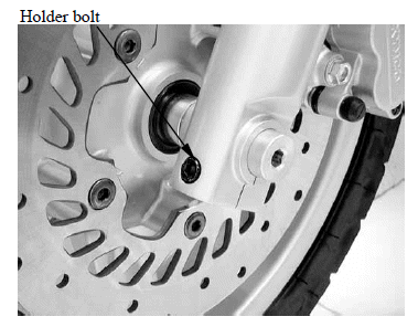
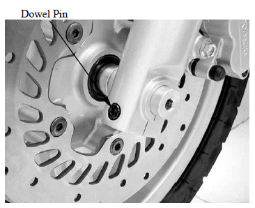
Loosen the front axle holder bolt.
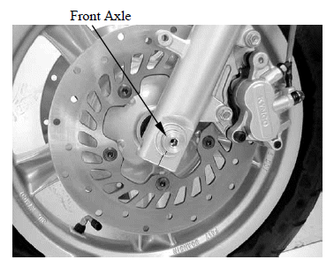
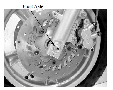
Loosen the front axle bolt.
Support the scooter securely using a hoist or equivalent and raise the front wheel off the ground.
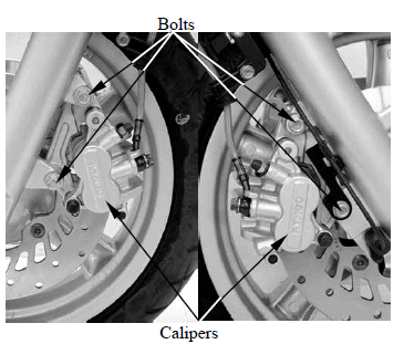
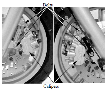
Remove the right and left mount bolts and front brake calipers.
Pull off the front axle out and remove the front wheel.
NOTE: Do not operate the front and rear brake lever after removing the front wheel.
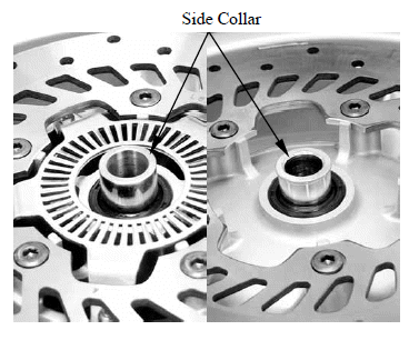
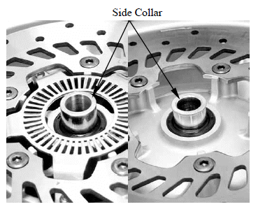
Remove the right and left side collar from the wheel hub.
INSTECTION
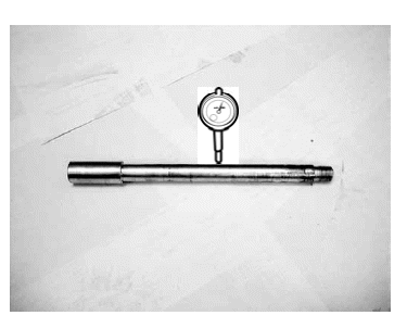
Axle
Place the axle in V-blocks and measure the runout.
Actual runout is 1/2 the total indicator reading.
Service limit: 0.20 mm (0.008 in)
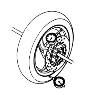
Wheel
Check the rim runout by placing the wheel in a truing stand.
Spin the wheel slowly and read the runout using a dial indicator.
Actual runout is 1/2 the total indicator reading.
Service limit:
Radial: 0.20 mm (0.008 in)
Axial: 0.20 mm (0.008 in)
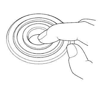
Wheel Bearing
Turn the inner race of each bearing with your finger.
The bearings should turn smoothly and quietly. Also check that the bearing outer race fits tightly in the hub.
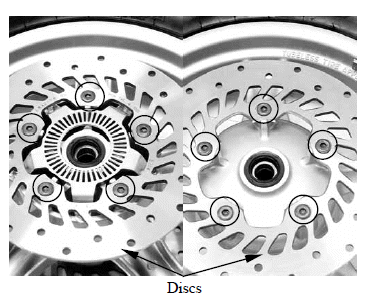
DISASSEMBLY
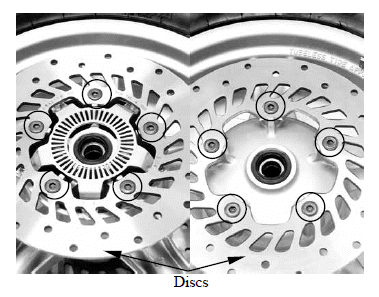
Remove the right and left disc bolts and brake discs.
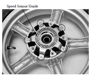
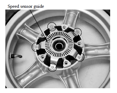
Remove the bolts and speed sensor guide.
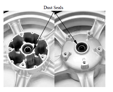
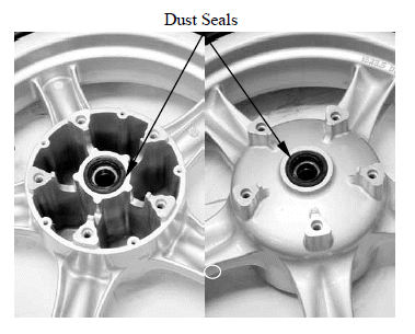
Remove the dust seals
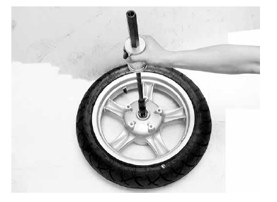
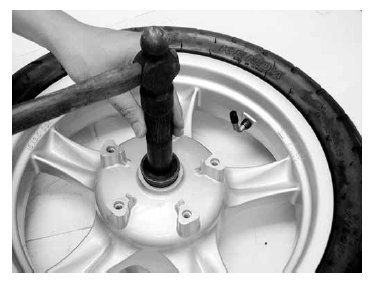
Install the bearing remover into the bearing.
Drive the bearing out of the wheel hub.
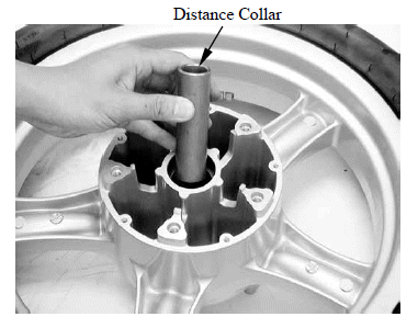
Remove the distance collar and drive out the other bearing.
Special tool: Bearing remover E037
NOTE: Replace the wheel bearings in pairs.
Do not reuse old bearings.
ASSEMBLY
Pack a new bearing cavities with grease.
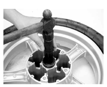
Drive the new left bearing squarely with the sealed side facing up until it is fully seated.
Special tool: Oil seal & bearing install driver E014
Install the distance collar.
Pack a new bearing cavities with grease.
Drive the new right bearing squarely with the sealed side facing up until it is fully seated.
Special tool: Oil seal & bearing install driver E014
Apply grease to the new dust seal lips.
Install the dust seals into the wheel hub until there are flush with the wheel hubs.
Install the speed sensor guide.
Install the plate blots and tighten them to the specified torque.
Torque: 10 N*m (1.0 kgf*m, 7 lbf*ft)
Install the brake discs into wheel hub.
Install new disc bolts and tighten them to the specified torque.
Torque: 42 N*m (4.3 kgf*m, 31 lbf*ft)
INSTALLATION
Install the side collars into the wheel hub.
Install the front wheel between the fork leg.
Install the front axle front left side.
Tighten the axle bolt to the specified torque.
Torque: 55 N*m (5.5 kgf*m, 40 lbf*ft)
Tighten the front axle holder to the specified torque.
Torque: 23 N*m (2.3 kgf*m, 17 lbf*ft)
Install the right and left front calipers onto the fork leg.
Install and tighten the new front caliper mount blots to the specified torque.
Torque: 32 N*m (3.2 kgf*m, 23 lbf*ft)
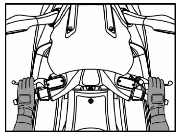
With the front brake applied, pump the fork up and down several times to seat the axle and check brake operation.
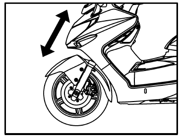
Check the brake operation by applying the brake lever.
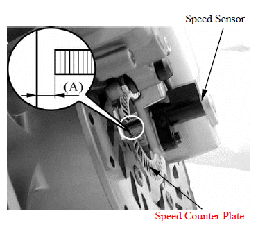
Measure the speed sensor to speed sensor guide clearance.
Standard (A): 0.3 - 1.2 mm (0.0012 - 0.048 in)
Adjust it if necessary.
See also:
 Kymco XCITING 500 - Service Manual > Schematic Drawing, Service Information
SCHEMATIC DRAWING SERVICE INFORMATION
Kymco XCITING 500 - Service Manual > Fork
REMOVAL Remove the front wheel. Remove the front fender. Remove the bolt and hose clamp. Remove the bolt and speed sensor (only right fork). Remove the upper fork pinch bolt.