 Kawasaki J300 - Service manual > Ignition System
WARNING The ignition system produces extremely high voltage.
Do not touch the spark plug, ignition coil or ignition coil lead while the engine is running, or you could receive a severe electrical shock.
NOTICE Do not disconnect the battery cables or any other electrical connections when the ignition switch is on, or while the engine is running. This is to prevent ECU damage.
Do not install the battery backwards. The negative side is grounded. This is to prevent damage to the ECU.
Crankshaft Sensor Removal
- Refer to the Stator Coil Removal.
Crankshaft Sensor Installation
- Refer to the Stator Coil Installation.
Crankshaft Sensor Inspection
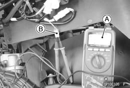
- Disconnect the crankshaft sensor lead connector (see Alternator Cover Removal).
- Connect a digital meter [A] to the crankshaft sensor lead connector [B].
Crankshaft Sensor Resistance
Connections:
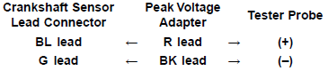
BL lead → G lead
Standard: 96 - 144 Ω @20ºC (68ºF)
If there is more resistance than the specified value, the coil has an open lead and must be replaced. Much less than this resistance means the coil is shorted, and must be replaced.
- Measure the resistance between the crankshaft sensor leads and chassis ground.
Any tester reading less than infinity (∞) indicates a short, necessitating replacement of the crankshaft sensor.
Crankshaft Sensor Peak Voltage Inspection
NOTE
- Be sure the battery is fully charged.
- Using the peak voltage adapter [A] is more reliable way to determine the condition of the crankshaft sensor than crankshaft sensor internal resistance measurements.
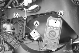
- Disconnect the crankshaft sensor lead connector (see Alternator Cover Removal).
- Connect a digital meter [B] to the peak voltage adapter.
Special Tool -
Peak Voltage Adapter: 57001-1415
Type: KEK-54-9-B
- Connect the adapter to the terminals of the crankshaft sensor lead connector [C].
Connections:
- Turn the engine stop switch to run position.
- Turn the ignition switch on.
- Pushing the starter button, turn the engine 4 - 5 seconds to measure the crankshaft sensor peak voltage.
- Repeat the measurements 5 or more times.
Crankshaft Sensor Peak Voltage
Standard: 0.9 V or more
If the reading is less than the standard, inspect the crankshaft sensor (see Crankshaft Sensor Inspection).
Ignition Coil Removal
- Remove the left side fairing (see Side Fairing Removal in the Frame chapter).
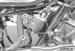
- Disconnect the spark plug cap [A].
- Remove the spark plug lead from the clamp [A].
- Disconnect the ignition coil lead connectors [B].
- Remove:
Ignition Coil Mounting Nuts [C]
Ignition Coil [D]
Ignition Coil Installation
- Install the ignition coil and tighten its nuts.
Torque - Ignition Coil Mounting Nuts: 12 N*m (1.2 kgf*m, 106 in*lb)
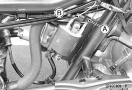
- Connect the ignition coil lead connectors.
BK Lead [A]
G/BR Lead [B] - Fit the plug cap securely.
- Pull up the spark plug cap lightly to make sure of the installation of the spark plug cap.
Ignition Coil Inspection
- Remove the ignition coil (see Ignition Coil Removal).
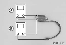
- Measure the primary winding resistance [A] as follows.
- Connect a tester between the ignition coil terminals.
- Measure the secondary winding resistance [B] as follows.
- Remove the spark plug cap from the spark plug lead.
- Connect a tester between the high tension lead and the ground terminal.
Ignition Coil Winding Resistance
Primary Windings: 2.38 - 3.22 Ω
Secondary Windings: 7.2 - 10.8 kΩ
If the tester does not read as specified, replace the ignition coil.
If the tester reads as specified, the ignition coil windings are probably good. However, if the ignition system still does not perform as it should after all other components have been checked, replace the coil with one known to be good.
- Check the spark plug lead for visible damage.
If the spark plug lead is damaged, replace the ignition coil.
- Install the spark plug cap to the spark plug lead securely.
Ignition Coil Primary Peak Voltage Inspection
NOTE
- Be sure the battery is fully charged.
- Disconnect the spark plug cap (see Ignition Coil Removal).
- Do not remove the spark plug.
- Measure the primary peak voltage as follows.
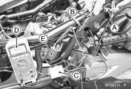
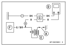
- Install the new spark plug [A] into the spark plug cap [B], and ground it onto the frame.
- Connect the peak voltage adapter [C] into a digital meter [D].
Ignition Coil [E]
ECU [F]
Special Tool -
Peak Voltage Adapter: 57001-1415
Type: KEK-54-9-B
Connections:
Adapter (R, +) → Ignition Coil Primary Lead Terminal
Adapter (G/BR, -) → Ignition Coil Ground Terminal
WARNING To avoid extremely high voltage shocks, do not touch the spark plugs or tester connections.
- Turn the ignition switch on.
- Pushing the starter button, turn the engine 4 - 5 seconds to measure the primary peak voltage.
- Repeat the measurements 5 or more times.
Ignition Coil Primary Peak Voltage
Standard: 120 V or more
If the reading is less than the specified value, check the following.
Ignition Coil (see Ignition Coil Inspection)
Crankshaft Sensor (see Crankshaft Sensor Inspection)
ECU (see ECU Power Supply Inspection in the Fuel System (DFI) chapter)
Spark Plug Removal
- Refer to the Spark Plug Replacement in the Periodic Maintenance chapter.
Spark Plug Installation
- Refer to the Spark Plug Replacement in the Periodic Maintenance chapter.
Spark Plug Condition Inspection
- Remove the spark plugs (see Spark Plug Replacement in the Periodic Maintenance chapter).
- Visually inspect the spark plugs.
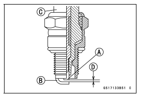
If the spark plug center electrode [A] and/or side electrode [B] are corroded or damaged, or if the insulator [C] is cracked, replace the plug.
If the spark plug is oily or has carbon built up on it, clean it. The plug may also be cleaned using high flash-point solvent and non metal brush (nylon etc.).
- Measure the gap [D] with a wire-type thickness gauge.
If the gap is incorrect, replace the spark plug.
Spark Plug Gap: 0.7 - 0.8 mm (0.028 - 0.031 in.)
- Use the standard spark plug or its equivalent.
Standard Spark Plug
Type: NGK CR7E
IC Igniter Inspection
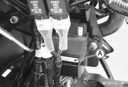
- The IC igniter is built in the ECU [A].
- Refer to the following items.
Ignition System Troubleshooting (see Ignition System section)
ECU Power Supply Inspection (see ECU Power Supply Inspection in the Fuel System (DFI) chapter)
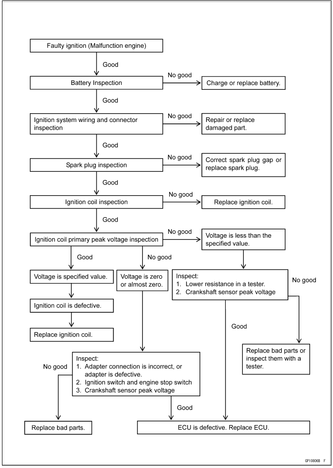
Ignition System Troubleshooting
Ignition System Circuit
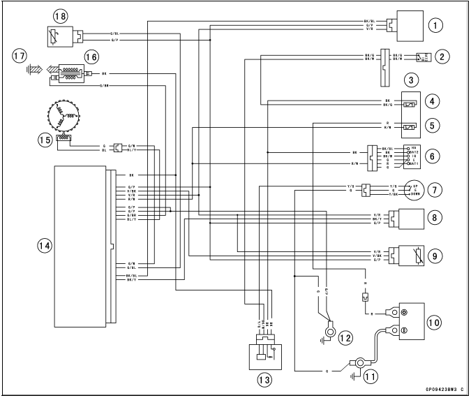
- Vehicle-down Sensor
- Engine Stop Switch
- Fuse Box
- Ignition Fuse 10 A
- Charging/ECU Fuse 30 A
- Ignition Switch
- Side Stand Switch
- Intake Air Pressure Sensor
- Throttle Sensor
- Battery 12 V 10 Ah
- Engine Ground
- Frame Ground 1
- ECU Relay
- ECU
- Crankshaft Sensor
- Ignition Coil
- Spark Plug
- Water Temperature Sensor (ECU)
See also:
 Kawasaki J300 - Service manual > Charging System
Alternator Cover Removal Drain: Engine Oil (see Engine Oil Change in the Periodic Maintenance chapter) Coolant (see Coolant Change in the Periodic Maintenance chapter) Remove: Storage Box (see Storage Box Removal in the Frame chapter) Lower Fairing (see Lower Fairing Removal In the Frame chapter) Exhaust Pipe (see Exhaust Pipe Removal in the Engine Top End chapter) Remove the band [A] and slide the dust cover [B]. Open the clamp [C]. Disconnect: Crankshaft Sensor Lead Connector [D] Alternator Lead Connector [E] Open the water hose clamp and disconnect the water bypass hose [A]. Loosen the water hose clamp screws and disconnect the water hoses [B]. Remove: Alternator Cover Bolts [C] Clamps [D] Alternator Cover [E]
Kawasaki J300 - Service manual > Electric Starter System
Starter Motor Removal Remove: Storage Box (see Storage Box Removal in the Frame chapter) Air Cleaner Box (see Air Cleaner Box Removal in the Fuel System (DFI) chapter) Slide the rubber cap [A]. Remove the starter motor cable terminal nut [B]. Remove the starter motor mounting bolts [C] and engine ground terminal [D]. Remove the starter motor [E].