 Kawasaki J300 - Service manual > Electrical System
Exploded View
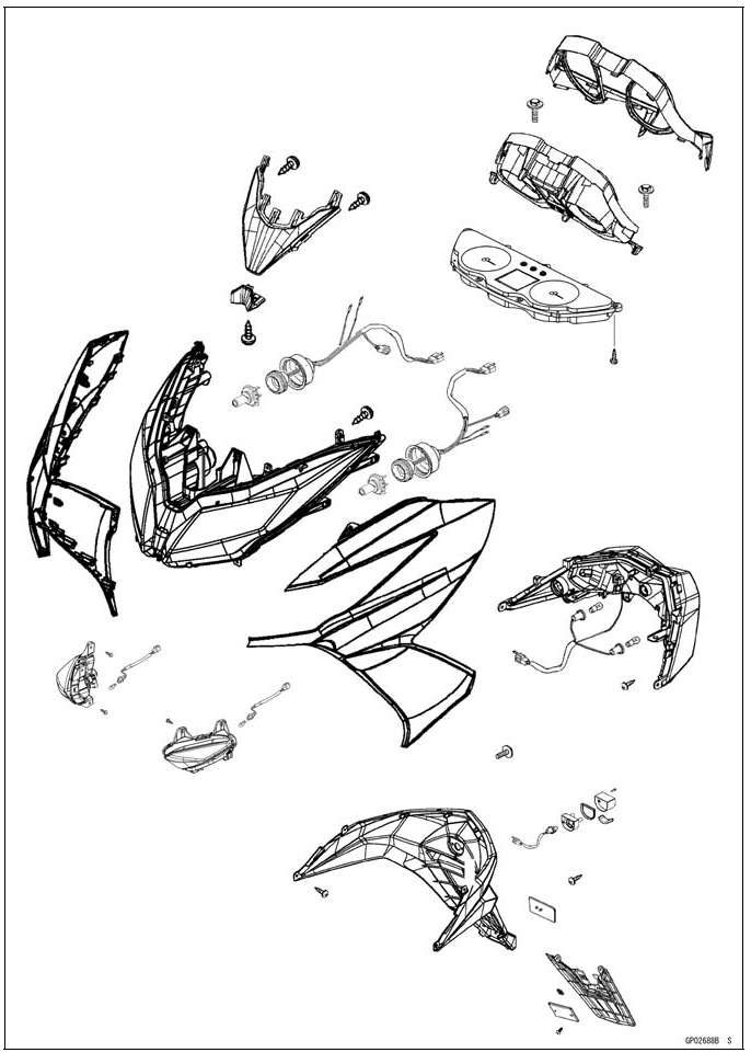
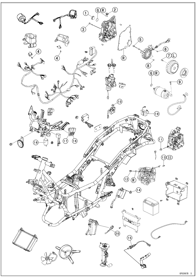
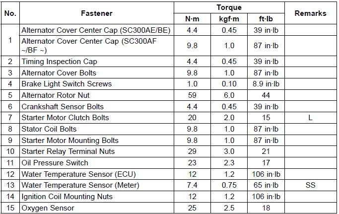
16. Turn Signal Relay
17. High Beam Headlight Relay
18. Low Beam Headlight Relay
19. Hazard Control Unit
20. Accessory Socket
L: Apply a non-permanent locking agent.
G: Apply grease.
R: Replacement Parts
SS: Apply silicone sealant.
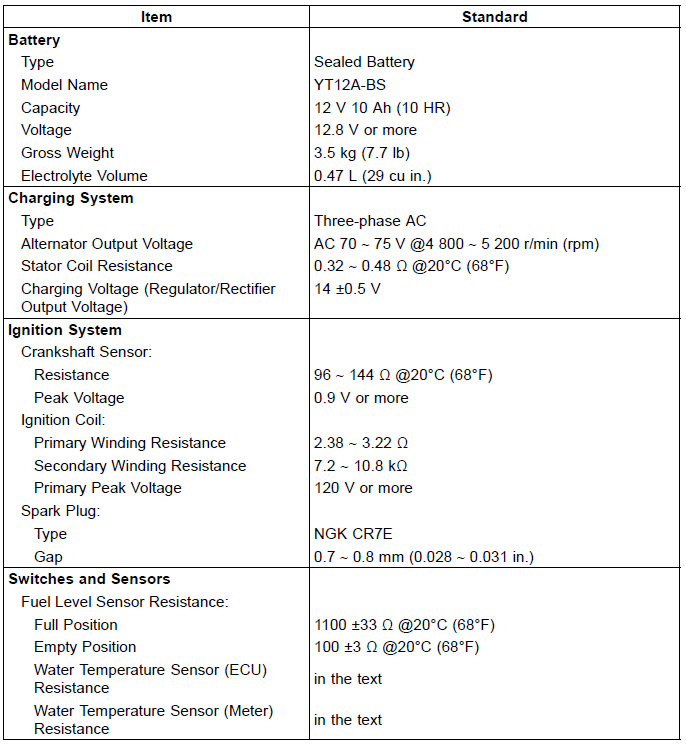
Specifications
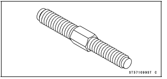
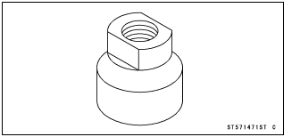
Special Tools and Sealant
Rotor Puller M18 Ă— 1.5, M16 Ă— 1.5: 57001-1099
Flywheel Puller, M28 Ă— 1.0: 57001-1471
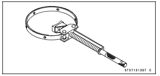
Flywheel Holder: 57001-1313
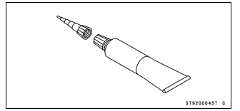
Liquid Gasket, TB1211F: 92104-0004
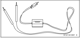
Peak Voltage Adapter: 57001-1415
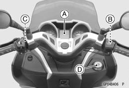
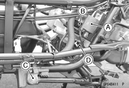
Parts Location
Meter Unit [A]
Front Brake Light Switch [B]
Rear Brake Light Switch [C]
Ignition Switch [D]
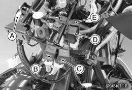
Horn [A]
High Beam Headlight Relay [B]
Low Beam Headlight Relay [C]
Starter Relay 1 [D]
Fan Relay [E]
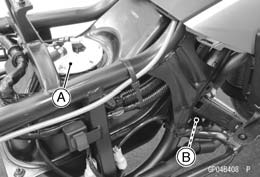
Fuel Pump/Fuel Level Sensor [A]
Fan Motor [B]
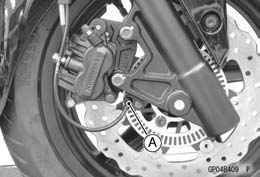
Speed Sensor (Front Wheel Rotation Sensor) [A]
Water Temperature Sensor (Meter) [A]
Water Temperature Sensor (ECU) [B]
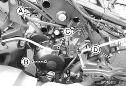
Ignition Coil [A]
Spark Plug [B]
Side Stand Switch [C]
Oil Pressure Switch [D]
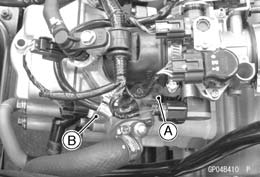
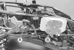
Starter Relay 2 [A]
Regulator/Rectifier [B]
Starter Motor [A]
Alternator [B]
Crankshaft Sensor [C]
Oxygen Sensor [D]
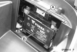
Fuse Box [A]
Battery [B]
Precautions
There are a number of important precautions that are musts when servicing electrical systems. Learn and observe all the rules below.
- Do not reverse the battery cable connections. This will burn out the diodes on the electrical parts.
- Always check battery condition before condemning other parts of an electrical system. A fully charged battery is a must for conducting accurate electrical system tests.
- The electrical parts should never be struck sharply, as with a hammer, or allowed to fall on a hard surface. Such a shock to the parts can damage them.
- To prevent damage to electrical parts, do not disconnect the battery cables or any other electrical connections when the ignition switch is on, or while the engine is running.
- Because of the large amount of current, never keep the starter button pushed when the starter motor will not turn over, or the current may burn out the starter motor windings.
- Take care not to short the cables that are directly connected to the battery positive (+) terminal to the chassis ground.
- Troubles may involve one or in some cases all items.
Never replace a defective part without determining what CAUSED the failure. If the failure was caused by some other item or items, they must be repaired or replaced, or the new replacement will soon fail again.
- Make sure all connectors in the circuit are clean and tight, and examine leads for signs of burning, fraying, etc. Poor leads and bad connections will affect electrical system operation.
- Measure coil and winding resistance when the part is cold (at room temperature).
Electrical Wiring
Wiring Inspection
- Visually inspect the wiring for signs of burning, fraying, etc.
If any wiring is poor, replace the damaged wiring.
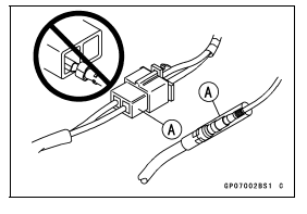
- Pull each connector [A] apart and inspect it for corrosion, dirt, and
damage.
If the connector is corroded or dirty, clean it carefully. If it is damaged, replace it.
- Check the wiring for continuity.
- Use the wiring diagram to find the ends of the lead which is suspected of being a problem.
- Connect a tester between the ends of the leads.
If the tester does not read about 0 Ω, the lead is defective.
Replace the lead or the wiring harness if necessary.
- Battery
- Charging System
- Ignition System
- Electric Starter System
- Lighting System
- Oil Pressure Warning System
- Meter, Gauge, Indicator Unit
- Switches and Sensors
See also:
 Kawasaki J300 - Service manual > Center Stand, Side Stand
Center Stand Removal Remove: Spring [A] Center Stand Bolts [B] and Nut (Both Sides) Center Stand [C]
Kawasaki J300 - Service manual > Battery
Battery Removal Turn the ignition switch off. Open the seat. Remove: Screws [A] Battery Cover [B] Remove: Bolts [A] Battery Case Cover [B] Slide the red cap [A]. Disconnect the negative (-) cable [B] and then positive (+) cable [C].