 Kawasaki J300 - Service manual > Meter, Gauge, Indicator Unit
Meter Unit Removal/Installation
- Refer to the Meter Cover Removal/Installation in the Frame chapter.
NOTICE Place the meter unit so that the face is up. If a meter unit is left upside down or sideways for any length of time, it will malfunction.
Meter Unit Disassembly
- Remove the meter unit (see Meter Unit Removal/Installation).
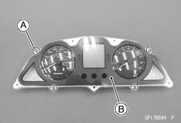
- Remove the screws [A] and separate the meter lens [B] and meter unit.
Electronic Combination Meter Unit Inspection
- Remove the meter unit with the meter cover installed (see Meter Unit Removal/Installation).
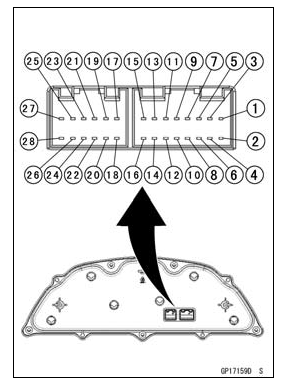
- Red Oil Pressure Switch (-)
- Meter Illumination Light (LED) (+)
- Water Temperature Sensor (+)
- Battery (+)
- Blue High Beam Indicator Light (LED) (+)
- Unused
- Green Right Turn Signal Indicator Light (LED) (+)
- Ignition (+)
- Green Left Turn Signal Indicator Light (LED) (+)
- Fuel Level Sensor (+)
- Unused
- Unused
- Tachometer Pulse
- Yellow ABS Indicator Light (LED) (-) (ABS Equipped Model)
- Unused
- Fuel Level Sensor (-)
- Unused
- Unused
- Yellow Engine Warning Indicator Light (LED) (-)
- Speed Sensor Pulse
- Ground (-)
- Speed Sensor Power Supply (+) (ABS Unequipped Model)
- Unused
- Unused
- Engine Stop Switch
- Water Temperature Sensor (-)
- Unused
- Unused
NOTICE Do not drop the meter unit. Place the meter unit so that it faces upward. If the meter unit is left upside down or sideways for a long time or dropped, it will malfunction. Do not short each terminals.
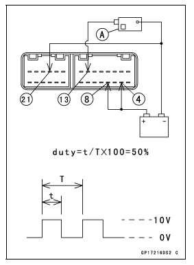
Check 1: Meter Unit Primary Operation Check
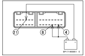
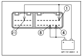
- Using the auxiliary leads, the 12 V battery to the meter unit connector
as follows.
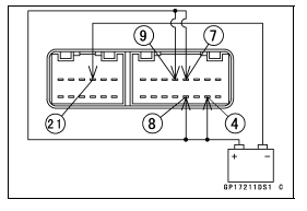
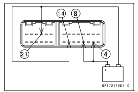
- Connect the battery positive (+) terminal to the terminal [4].
- Connect the battery negative (-) terminal to the terminals [21].
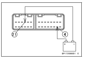
- Connect the terminal [8] to the battery (+) terminal.
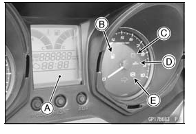
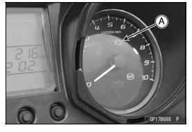
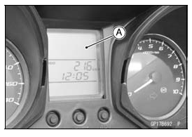
- Check the following items.
- The speedometer and tachometer needles momentarily point their last readings and back to the minimum position.
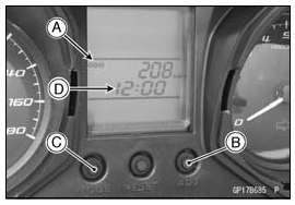
- All the LCD (Liquid Crystal Display) segments [A] go on for a few seconds.
- The yellow fuel level warning indicator light (LED) [B], red battery voltage warning indicator light (LED) [C] and yellow oil service indicator light (LED) [D] go on for a few seconds.
- For ABS equipped model, the yellow ABS indicator light (LED) [E] goes on.
If the meter unit does not work, replace the meter unit.
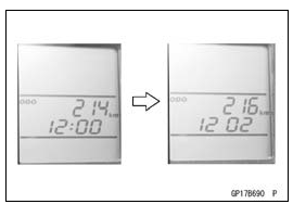
Check 2: ADJ Button Operation Check
- Connect the leads in the same circuit as Check 1.
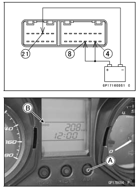
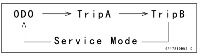
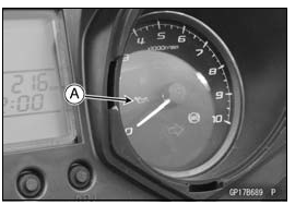
- By pushing the ADJ button [A] for 2 seconds, check that the display [B] changes as follows.
If the display function does not work, replace the meter unit.
Check 3: Clock Setting Check
- Connect the leads in the same circuit as Check 1.

- Set the ODO mode [A] by pushing the ADJ button [B] for 2 seconds.
- Push the MODE button [C] and ADJ button simultaneously for more than 2
seconds to adjust the clock [D].
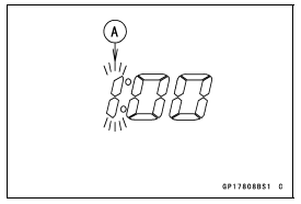
- The hour display only blinks.
- By pushing the ADJ button each time, check that the hour display [A] changes.
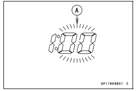
- By pushing the MODE button, check that the hour display decides and minute display [A] starts blinking.
- By pushing the ADJ button each time, check that the minute display changes.
- Push the MODE button and ADJ button simultaneously for more than 2
seconds. The displays stop blinking and the clock starts working.
If the display function does not work, replace the meter unit.
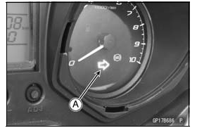
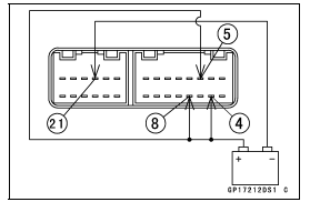
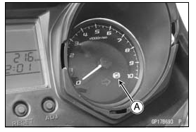
Check 4: Green Turn Signal Indicator Light (LED) Inspection
- Connect the leads in the same circuit as Check 1.
- Connect the terminal [7] (right) or [9] (left) to the battery (+) terminal.
- Check that the green turn signal indicator light (LED) [A] goes on.
If the indicator light (LED) does not go on, replace the meter unit.
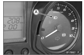
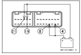
Check 5: Blue High Beam Indicator Light (LED) Inspection
- Connect the leads in the same circuit as Check 1.
- Connect the terminal [5] to the battery (+) terminal.
- Check that the blue high beam indicator light (LED) [A] goes on.
If the indicator light (LED) does not go on, replace the meter unit.
Check 6: Yellow Engine Warning Indicator Light (LED) Inspection
- Connect the leads in the same circuit as Check 1.
- Connect the terminal [19] to the battery (-) terminal.
- Check that the yellow engine warning indicator light (LED) [A] goes on.
If the indicator light (LED) does not go on, replace the meter unit.
Check 7: Red Oil Pressure Warning Indictor Light (LED) Inspection
- Connect the leads in the same circuit as Check 1.
- Connect the terminal [1] to the battery (-) terminal.
- Check that the red oil pressure warning indicator light (LED) [A] goes
on.
If the indicator light (LED) does not go on, replace the meter unit.
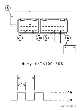
Check 8: Speedometer Inspection
- Connect the leads in the same circuit as Check 1.
- The speed equivalent to the input frequency is indicated in the
oscillator [A], if the square wave is input into terminal [20].
- Indicates approximately 60 km/h if the input frequency is approximately 550 Hz.
If the meter function does not work, replace the meter unit.
NOTE
- The input frequency of the oscillator adds the integrated value of the odometer.
Check 9: Odometer Check
- Check the odometer with the speedometer check in the same way.
If value indicated in the odometer is not added, replace the meter unit.
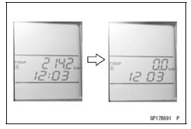
Check 10: Trip A/Trip B Meter Check
- Check the trip meter with the speedometer in the same way.
If value indicated in the trip meter is not added, replace the meter unit.
- Check that when the RESET button is pushed for more than 2 seconds, the
figure display turns to 0.0.
If the figure display does not indicate 0.0, replace the meter unit.
Check 11: Tachometer Inspection
- Connect the leads in the same circuit as Check 1.
- The engine speed (rpm) equivalent to the input frequency is indicated in
the oscillator [A], if the square wave is input into terminal [13].
- Indicates approximately 4 000 rpm if the input frequency is approximately 67 Hz.
If the meter function does not work, replace the meter unit.
Check 12: Meter Illumination Light (LED) Inspection
- Connect the leads in the same circuit as Check 1.
- Connect the terminal [2] to the battery (+) terminal.
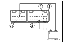
- Check that the meter illumination light (LED) [A] goes on.
If the light (LED) does not go on, replace the meter unit.
Check 13: Yellow ABS Indicator Light (LED) Inspection (ABS Equipped Model)
- Connect the leads in the same circuit as Check 1.
- Connect the terminal [14] to the battery (-) terminal.
- Check that the yellow ABS indicator light (LED) [A] goes on.
If the indicator light (LED) does not go on, replace the meter unit.
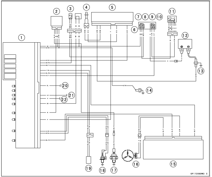
Meter Circuit
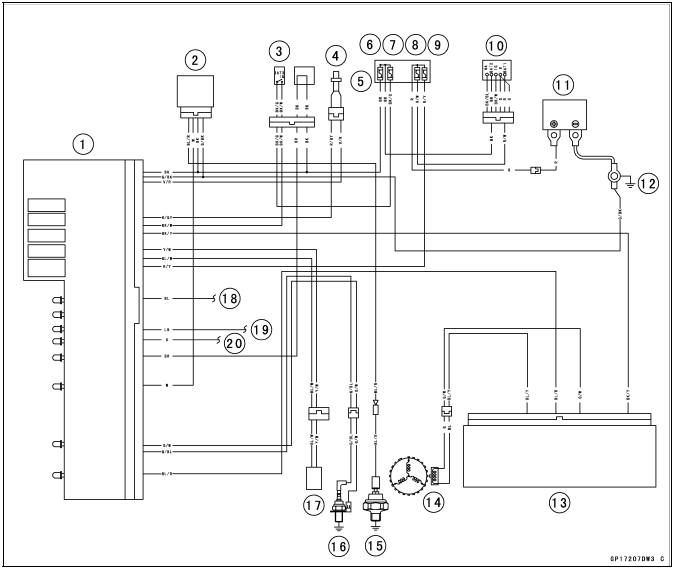
- Meter Unit
- Oil Pressure Warning Indicator Light Controller
- Engine Stop Switch
- Speed Sensor
- Fuse Box
- Main Fuse 15 A
- Ignition Fuse 10 A
- Charging/ECU Fuse 30 A
- Headlight Relay Fuse 15 A
- Ignition Switch
- Battery 12 V 10 Ah
- Engine Ground
- ECU
- Crankshaft Sensor
- Oil Pressure Switch
- Water Temperature Sensor (Meter)
- Turn Signal Relay
- to Dimmer Switch and Passing Button
- to Turn Signal Light Switch (Right)
- to Turn Signal Light Switch (Left)
Meter Circuit (ABS Equipped Model)
- Meter Unit
- Oil Pressure Warning Indicator Light Controller
- Engine Stop Switch
- Front Wheel Rotation Sensor
- ABS Hydraulic Unit
- Fuse Box
- Main Fuse 15 A
- Ignition Fuse 10 A
- Charging/ECU Fuse 30 A
- Headlight Relay Fuse 15 A
- Ignition Switch
- Battery 12 V 10 Ah
- Engine Ground
- Frame Ground 1
- ECU
- Crankshaft Sensor
- Oil Pressure Switch
- Water Temperature Sensor (Meter)
- Turn Signal Relay
- to Dimmer Switch and Passing Button
- to Turn Signal Light Switch (Right)
- to Turn Signal Light Switch (Left)
See also:
 Kawasaki J300 - Service manual > Oil Pressure Warning System
Oil Pressure Warning Indicator Light Controller Removal Remove the front fairing (see Front Fairing Removal in the Frame chapter). Disconnect the connector [A]. Remove the oil pressure warning indicator light controller [B].
Kawasaki J300 - Service manual > Switches and Sensors
Brake Light Timing Inspection Refer to the Brake Light Switch Operation Inspection in the Periodic Maintenance chapter. Switch Inspection Using a tester, check to see that only the connections shown in the table have continuity. For the switch housings and the ignition switch, refer to the tables in the Wiring Diagram.