 Kymco XCITING 500 - Service Manual > Crankcase Separation
Remove the parts required for crankcase separation.
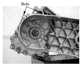
Remove the twelve bolts from left crankcase.
Loosen the bolts in a crisscross pattern in several steps.
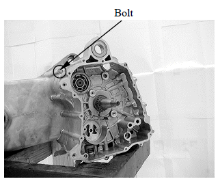
Remove the bolt from right crankcase.
Place the crankcase assembly with the left side down and separate the right crankcase from the left crankcase.
Separate the right crankcase from the left crankcase while tapping them at several locations with a soft hammer.
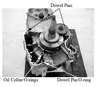
Remove the dowel pins and O-ring.
Remove the oil collar and O-rings from the left crankcase.
Clean of the sealant from the left and right crankcase mating surfaces.
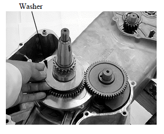
Remove the washer from the crankshaft.
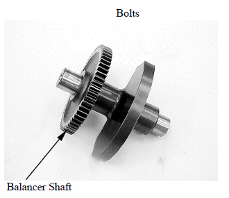
Remove the balancer shaft from the left crankcase.
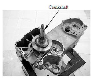
Remove the crankshaft from the left crankcase.
RIGHT CRANKCASE DISASSEMBLY
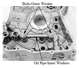
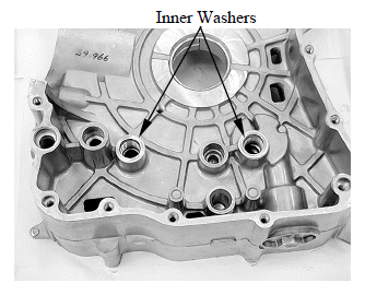
Remove the two bolts, outer washer, oil pipe and inner washers.
RIGHT CRANKCASE ASSEMBLY
Install the inner washers onto the right crankcase.
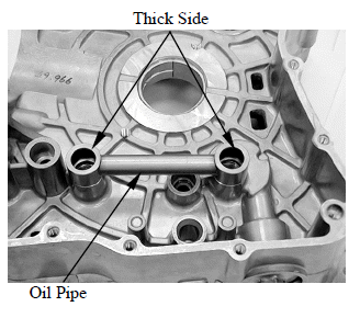
Install the oil pipe with the thick side face upward.
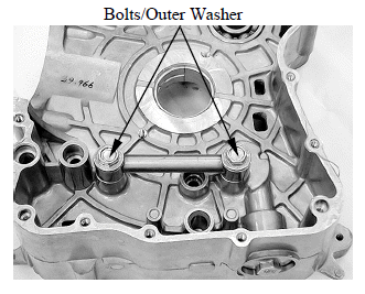
Install the outer washers and two bolts.
Tighten the two bolts to the specified torque.
Torque: 43 N*m (4.3 kgf*m, 31 lbf*ft)
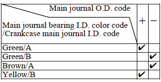
CRANKSHAFT/CRANKCASE SELECTION
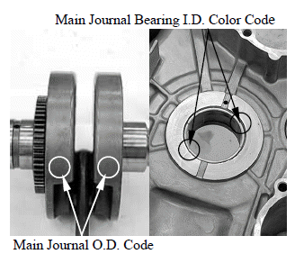
Crankcase and crankshaft are select fitted.
Record the main journal O.D. code (- or +) Record the main journal bearing I.D. color code (green, brown or yellow).
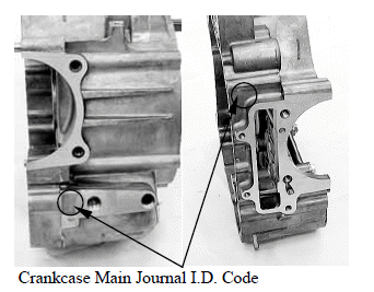
Record the right or left crankcase main journal I.D. code (A or B).
If the crankcase and/or crankshaft are replaced, select them with the following fitting table.
The " "
mark in the table indicates that mating is possible in the crossed code.
"
mark in the table indicates that mating is possible in the crossed code.
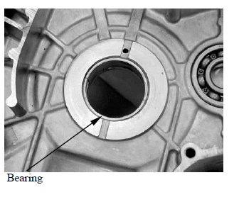
MAIN BEARING INSPECTION
Inspect the bearing inserts for unusual wear, damage or peeling and replace the crankcase if necessary.
Main bearing oil clearance
Clean off any oil from the main bearing inserts and crankshaft journals.
Measure and record the crankshaft main journal O.D..
Measure and record the main bearing I.D..
Calculate the oil clearance by subtracting the journal O.D. from bearing I.D..
Standard: 0.025 - 0.041 mm (0.001 - 0.0016 in)
Service limit: 0.07 mm (0.003 in)
Replace the crankcase if the service limit is exceeded.
Select the replacement crankcase.
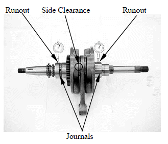
CRANKSHAFT INSPECTION
Measure the connecting rod big end side clearance.
Service limit: 0.8 mm (0.031 in)
Measure the crankshaft runout.
Service limit: 0.06 mm (0.002 in)
BALANCER SHAFT INSPECTION
Inspect the balance shaft gear teeth.
Burrs/chips/roughness/wear → Replace.
BALANCER SHAFT BEARING REPLACMENT
Remove the crankshaft and balancer shaft.
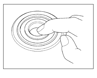
Turn the inner race of each bearing with your finger.
The bearings should turn smoothly and quietly. Also check that the bearing outer race fits tightly in the crankcase.
Replace the bearings if the races does not turn smoothly and quietly, or if they fit loosely in the crankcase.
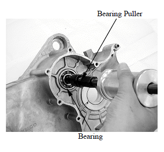
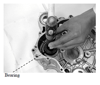
Remove the balancer shaft bearing from the left crankcase using the special tool.
Special tool: Bearing puller E037
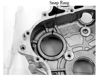
Remove the bearing snap ring from right crankcase.
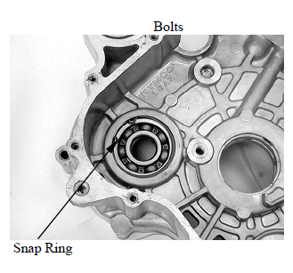
Remove the balancer shaft bearing from the right crankcase.
Install the snap ring into the right crankcase.
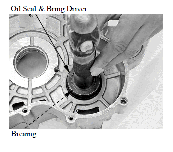
Install the new bearings to the right and left crankcase using special tool.
Special tool: Oil seal & bearing driver E014
See also:
 Kymco XCITING 500 - Service Manual > Schematic Drawing, Service Information
SCHEMATIC DRAWING SERVICE INFORMATION
Kymco XCITING 500 - Service Manual > Crankcase Assembly
Install the crankshaft to the left crankcase. Install the balancer shaft to align the punch mark with the "O" mark on the crankshaft.